



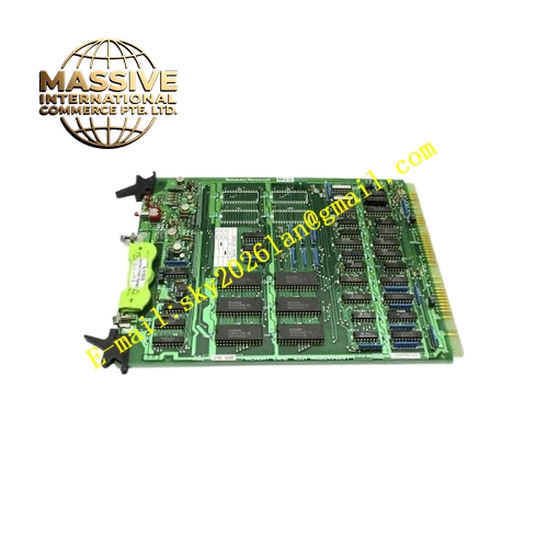
Description
Honeywell 82408667-003
Technical Specifications
- Input Power: 24VDC from S9000 rack power supply
- Output Power Rail: 5VDC logic rail and 24VDC field I/O rail
- Maximum Total Output Current: Matched with S9000 rack rating
- Operating Ambient Temperature: 0°C to +60°C
- Storage Temperature: -40°C to +85°C
- Relative Humidity: 5% to 90% RH non-condensing
- Mounting Type: Fixed chassis installation inside S9000 rack
- Certification: UL, CE, RoHS
Functional Features It distributes stable 5VDC and 24VDC power to each slot of S9000 rack. It carries independent fuse protection for each power rail. It monitors bus voltage and total output current continuously. It triggers power fault alarm when under-voltage or over-current condition occurs. It provides front panel LED indicators for 5VDC rail active, 24VDC rail active and fault. It supports hot removal of individual I/O cards without affecting power supply of other slots. It uploads power bus fault information to S9000 main controller. It suppresses power rail noise and ripple for I/O modules.
Application Scenarios S9000 main control rack power distribution backplane Petrochemical plant I/O expansion rack Chemical batch process controller chassis Refinery auxiliary control cabinet Water treatment plant distributed I/O rack
Performance Parameters
- Voltage Regulation Accuracy: ±2%
- Mean Time Between Failures: 820000 hours
- Insulation Resistance: Greater than 1000 MΩ
- ESD Immunity: 8kV contact discharge
Material Composition FR4 flame retardant conformal coated multilayer PCB Power distribution copper trace array Fuse holders and replaceable fuses Voltage and current sensing circuit TVS surge suppression components Gold plated slot connectors for I/O paddle cards Metal mounting bracket fixed to rack chassis Multi-color LED status indicators
Structural Features Flat rack-mounted backplane board form factor. Wide copper traces are used for power distribution to reduce voltage drop. Each slot has independent power feed point. Separate trace zones for 5VDC logic power and 24VDC field power. Anti-key structure on each slot prevents reverse insertion. Metal bracket provides mechanical support and shielding. Front status LED group shows global power rail status.
Working Principle 24VDC input power enters the backplane board from rack power supply module. Internal power distribution circuit splits power into 5VDC logic rail and 24VDC I/O rail. Each slot receives power supply through gold plated slot connector. Current sensing circuit measures total load current of each rail. If current exceeds fuse rating or voltage drops below threshold, fault flag is generated and sent to controller. Fuse cuts off power rail to protect other modules from damage under short-circuit condition.
Installation Requirements Wear anti-static wrist strap before installation. Fix the backplane board to designated mounting position inside rack chassis with standard screws. Complete power input wiring from power supply module. Check all slot connectors for mechanical alignment. Install correct rated fuses for each power rail. Power on rack and verify both power rail LED steady on. Insert I/O cards one by one and confirm normal power supply.
Usage Notes Only replace fuses with same rated specification. Do not modify copper trace or bypass fuse protection. Keep slot connectors clean and free from conductive dust. Do not overload rack power rail beyond rated current. Replace backplane board if power rail voltage drops abnormally under normal load.







