



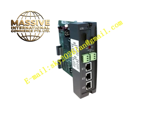
Description
Honeywell 900C32-0140
Technical Specifications
- Compatible rack: Standard HC900 expansion I/O rack
- Bus connection: Dedicated flat expansion cable connects to the main CPU
- Maximum expansion distance: 5 meters
- Supported module count: Up to 8 I/O modules per rack
- Supply power: 5 V DC from backplane
- Operating temperature: 0 °C to +60 °C
- Bus rate: 2 Mbps
Functional Features Transparent bus extension, the main CPU automatically recognizes expansion rack modules without additional configuration. On-board signal shaping circuit compensates for signal attenuation over long cable runs. Expansion connection fault automatic diagnosis, triggers communication loss alarm. On-board LEDs indicate expansion link connection and communication activity status. Supports hot-swap replacement, individual module replacement does not disrupt remaining rack operation.
Application Scenarios I/O point expansion for HC900 systems Communication connection for cabinet-separated main and field I/O racks Spare part replacement for old expansion rack interface board faults Rack communication unit for control system capacity expansion retrofits
Performance Parameters
- Bus delay: ≤2 ms
- Signal shaping compensation: Signal amplitude compensation for 10-meter cable runs
- Fault detection response: ≤100 ms
- Isolation withstand voltage: 1500 VAC
Material Composition FR4 PCB substrate Bus signal buffer chip Gold-plated bus connector Optocoupler isolation devices ABS flame retardant plastic enclosure
Structural Features Long rectangular DIN-rail mount module. Installed in the dedicated leftmost slot of the expansion rack. Side expansion cable interface connects to the main CPU. Front panel LEDs indicate link status and communication. Bottom contacts mate directly to the rack backplane.
Working Principle The main CPU sends I/O bus data through the expansion cable to this interface module. The on-board signal buffer and shaping circuit amplifies and restores signal distorted by long-distance transmission, then distributes the signal through the backplane to all expansion I/O modules. Return data from expansion modules is packaged by the module and sent back to the main CPU. Link monitoring circuit continuously checks expansion cable connection status; cable disconnection generates a communication fault flag for upload to the CPU.
Installation Requirements Install the module in the dedicated leftmost slot of the expansion rack. Plug dedicated expansion cables between the main unit and this module, lock the connector clips. Check LED status after power-up, confirm the main unit detects all expansion I/O modules. Route expansion cables separately from high-power cabling.
Usage Notes Expansion cable length must not exceed 5 meters; longer runs cause signal distortion and communication failure. Hot-swapping expansion cables causes the main unit to drop the rack, triggering process alarms. If the interface board fails, the entire expansion rack goes offline; after replacement, re-verify all I/O point status.







