



Description
Honeywell CC-TCNT01
Technical Specifications Rated supply voltage 24VDC; operating current 0.311A at 24VDC; signal isolation voltage 2500VAC between field side and backplane side; compatible with analog 4-20mA, 0-10V and discrete 24VDC signals; operating temperature range 0℃ to 60℃; storage temperature range -40℃ to 85℃; relative humidity 5% to 95% non-condensing; mounting form is standard single-slot rack installation; certification includes UL, CE and Class I Division 2 hazardous area approval.
Functional Features It concentrates all field instrument wiring onto screw terminal blocks for convenient wiring and maintenance. It integrates transient suppression circuits to absorb voltage surges introduced from field cables. It routes field signals to the paired IOM module through the internal backplane connector. It supports hot-swap of upper I/O modules without disconnecting field wiring. It carries on-board circuit diagnostics to detect open terminals and short-circuit faults on field circuits. It supports 1:1 redundant I/O pair configuration for critical measurement and control points.
Application Scenarios Field signal termination for refinery Experion PKS control cabinets; analog and discrete signal junction for chemical plant C300 controller racks; remote I/O cabinet wiring base for power plant auxiliary control systems; replacement spare termination unit for upgraded legacy Experion PKS projects.
Performance Parameters Signal bandwidth meets standard process control loop scan requirements; isolation circuit blocks field ground loop interference; terminal contact resistance maintains stable value under long-term vibration; fault diagnosis signal uploads to Experion station within one controller scan cycle.
Material Composition Main base housing uses flame-retardant engineering plastic; internal circuit board adopts FR4 high-temperature flame-retardant substrate with conformal coating; terminal screws and conductive shrapnel use tin-plated copper alloy; backplane connector pins are gold-plated; metal fixing brackets use cold-rolled steel with anti-rust coating.
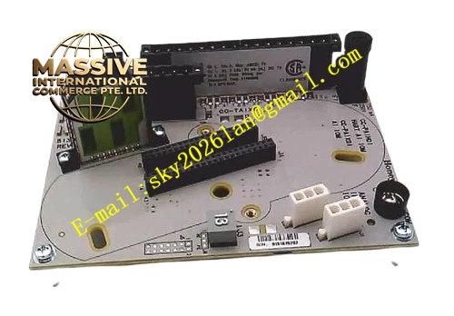
Structural Characteristics Single-width horizontal rack base with fool-proof keying structure to prevent mismatched IOM insertion; front panel with terminal marking labels and module status indicator holes; screw terminals arranged in orderly rows for cable access; rear integrated male backplane connector for mating with IOM cards; side elastic latches for locking to rack rail.
Working Principle Field instrument cables connect to the screw terminals on the IOTA base. Signals pass through surge suppression and filtering circuits inside the base, then transmit to the upper I/O module through the backplane connector. The diagnostic circuit continuously monitors line state of each channel and transmits fault information to the IOM module. The IOTA does not perform signal conversion; it only completes signal distribution, protection and wiring transfer.
Installation Requirements Mount the base on standard 19-inch control cabinet rack rails. Confirm keying notch matches the IOM module type before installation. Torque all field terminal screws to the value specified in Honeywell installation manual. Separate analog signal cables and high-power AC cables in the cabinet. Cabinet protective grounding resistance must be less than or equal to 4Ω.
Usage Notes Do not apply field voltage exceeding rated range to the terminal blocks. Wear anti-static wrist strap when installing and removing matched IOM modules. Do not remove the IOTA base while field cables remain energized. Clean terminal blocks regularly to prevent dust accumulation causing poor contact.







