



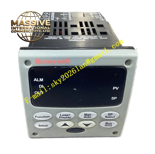
Description
Honeywell DC3200-C0-000R-100-00000-00-0
Technical Specifications
- Panel Dimension: 1/4 DIN, 96mm × 96mm panel cutout
- Input Type: Universal input, thermocouple, RTD, 4-20mA, 0-10VDC
- Control Output: Relay contact output
- Rated Relay Contact: 250VAC, 3A resistive load
- Power Supply: 90VAC to 250VAC, 50/60Hz
- Working Temperature: 0°C to +55°C
- Storage Temperature: -40°C to +85°C
- Humidity: 5% to 90% RH non-condensing
- Front Panel Protection: IP55, optional NEMA4X IP66
- Scan Cycle: 100ms
- Certification: UL, C-UL, CE, RoHS
Functional Features Advanced Accutune III auto-tune algorithm with fast load response. It supports heat/cool control, limit control and ramp soak profile programming. It supports up to 4 independent alarm functions. It provides sensor break diagnostic for thermocouple and RTD. It supports manual / automatic bumpless transfer. It supports infrared configuration port and RS485 Modbus communication option. It supports PIE software offline configuration and parameter upload/download. It has configurable relay action mode for normally open and normally closed.
Application Scenarios Industrial oven and heat treatment furnace temperature control Injection molding machine barrel temperature control Chemical small reactor heating control Drying tunnel temperature regulation Food baking equipment temperature control Packaging machine thermal sealing temperature control
Performance Parameters
- Measurement Accuracy: ±0.20% full scale
- PID resolution: 0.01%
- Insulation Resistance: greater than 100 MΩ
- Mean Time Between Failures: 910000 hours
- Relay Contact Life: 100000 operations at rated load
- Alarm detection response time: less than 0.4s
Material Composition ABS flame retardant front panel with polycarbonate display window FR4 flame retardant PCB 32-bit microprocessor chip Signal conditioning circuit Electromagnetic relay for control output High brightness digital LED display Silicone sealing gasket Metal panel locking bracket
Structural Features Square 1/4 DIN panel mount housing. Front panel has dual digital display and function operation keys. Rear side is screw terminal block for power, sensor input and relay output. Silicone gasket is installed between panel and cabinet opening. Two side metal clips lock the controller firmly. Internal circuit partitions separate power circuit, signal input circuit and relay output circuit.
Working Principle Field sensor signal is sent to universal input conditioning circuit. The controller converts analog sensor signal into digital process value. The microprocessor compares PV and SP value, executes PID algorithm and drives relay contact to turn on or off heating or cooling load. Auto-tune function automatically identifies process characteristic and optimizes PID parameters. When process value reaches alarm threshold, alarm relay triggers alarm signal.
Installation Requirements Make 96mm × 96mm panel cutout. Insert controller from front side, install side locking brackets and tighten. Wire sensor signal, AC power and load circuit to rear terminals. Select sensor type and set PID, alarm parameters through keypad or PIE software. Power on and test relay action and display function. Keep controller away from high temperature and strong electromagnetic interference source.
Usage Notes Relay contact load cannot exceed 250VAC 3A rating. Inductive load must add RC absorption circuit at contact terminals. Thermocouple wiring must use matching compensation wire. Do not connect high voltage to input terminals. Replace relay module when contact ablation appears after long time operation.







