



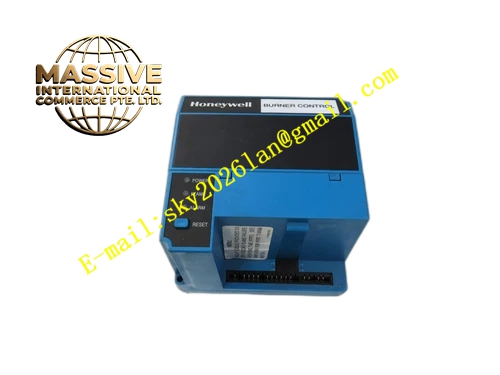
Description
Honeywell EC7823A1004
Technical Specifications
- Brand: Honeywell
- Model: EC7823A1004
- Product Type: Flame relay switch
- System Family: Honeywell 7800 series combustion control
- Function: Provides switch output according to flame status
- Supply Voltage: 220 to 240 Vac
- Voltage Tolerance: +10%, -15%
- Frequency: 50/60 Hz ±10%
- Operating Temperature: -40°C to 60°C
- Storage Temperature: -40°C to 66°C
- Humidity: Up to 85% RH, non-condensing
- Vibration Rating: 0.5 g environment
- Relay Module Weight: Approximately 0.73 kg unpacked
- Mounting: Universal base Q7800 series
Functional Features
- Detects flame presence through a compatible flame signal amplifier and flame detector.
- Provides relay switch output when flame is present.
- Removes or changes relay output when flame is lost.
- Integrates with EC7800 or RM7800 combustion program controllers.
- Supports status indication through an optional display panel.
- Allows remote signaling and remote control functions depending on system configuration.
- Supports dynamic component checking within the 7800 control system.
- Modular design enables replacement without rewiring the entire base.
Application Scenarios
- Industrial gas burners
- Oil-fired burners
- Boiler combustion systems
- Furnace and oven burners
- Process heater flame monitoring
- Burner retrofit and maintenance projects
- Systems requiring flame-proven switch signals for interlocking
Performance Parameters
- Supply voltage: 220 to 240 Vac
- Frequency: 50/60 Hz
- Operating temperature: -40°C to 60°C
- Humidity: 85% RH maximum, non-condensing
- Vibration tolerance: 0.5 g
- Relay module power dissipation: up to 10 W maximum for the 7800 relay module family
- Maximum total connected load for the 7800 system: up to 2000 VA depending on configuration
- Flame response behavior depends on the selected flame amplifier and detector
- Exact safety timing depends on the installed purge timing card and system setup
Material Composition
- Industrial relay module housing
- Flame status logic circuitry
- Relay output contacts
- Base interface connectors
- Status indication interface
- Flame amplifier integration through the 7800 system
- Mounting and locking hardware
Structural Features
- Plug-in module design for the 7800 series universal base.
- Front-facing status indication depending on installed display module.
- Compatible with Q7800A or Q7800B universal bases.
- Works with plug-in flame signal amplifiers and flame detectors.
- Compact relay module suitable for control panel or field-mounted base installation.
- Modular architecture allows separate replacement of controller, relay, display, and timing card.
Working Principle
The 7800 combustion control system monitors the burner flame through a flame detector and flame signal amplifier. The EC7823A1004 receives the processed flame signal and provides a relay switch output when flame is proven. If the flame signal is lost during operation, the relay changes state to indicate flame failure. The combustion program controller then takes the required safety action, such as shutting down the fuel supply and generating an alarm. The EC7823A itself functions as a flame-proven relay switch rather than a standalone burner program controller.
Installation Requirements
- Use only with compatible Honeywell 7800 series components.
- Install on a Q7800 universal base matched to the application.
- Confirm supply voltage is 220 to 240 Vac, 50/60 Hz.
- Match the flame detector and flame amplifier to the fuel type and burner design.
- Install the correct purge timing card for the required pre-purge duration.
- Wire flame detector, fuel valves, ignition, and interlocks according to the approved schematic.
- Verify flame signal stability during commissioning.
- Test flame failure response before placing the burner in automatic service.







