



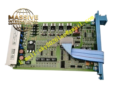
Description
Honeywell FS-SDOL-0424
Technical Specifications
- Channel Number: 4 supervised output channels
- Output Voltage: 24V DC regulated
- Max Channel Current: 200mA
- Loop Supervision: End of line resistor monitoring
- Isolation Voltage: 500V AC
- Operating Temperature: -10°C to +60°C
- Humidity: 5% to 95% non-condensing
- Communication Bus: FS series fire safety rack backplane
Functional Features Constant supervision of end-of-line resistor to detect wire break and short circuit. Per channel overcurrent protection with fault latch. Status readback of actual output voltage and loop resistance. Front panel visual LED for power, channel active and fault indication. Compliant with fire system supervision wiring standard. Fault event timestamp uploaded to fire controller event log.
Application Scenarios Fire suppression solenoid release circuit supervised output Fire alarm horn and visual strobe signal control Smoke damper and fire shutter actuator drive Fire & gas detection system alarm output Replacement spare for FS fire control rack I/O subsystem
Performance Parameters
- Supervision resistance detection range: Predefined EOL resistor window
- Response time for alarm activation: <2ms
- Fault detection response: <3ms
- Loop supervision sampling interval: 200ms
Material Composition FR4 UL94V0 PCB, high precision sampling resistors, optocoupler isolation devices, power switching MOSFET, TVS surge suppression diodes, screw type terminal block, fire rated plastic housing.
Structural Features Plug-in rack card compatible with FS series fire rack slots. Detachable wiring terminal block. Front panel LED indicators grouped for power and each channel. Internal layout separates fire safety logic zone and field output power zone. Card edge gold contact for backplane bus connection.
Working Principle Fire controller sends activation command through rack backplane. Onboard circuit enables output power to field supervised loop. Sampling circuit continuously measures total loop resistance including end-of-line resistor. If resistance falls outside calibrated window, fault flag is asserted and sent back to fire controller. Overcurrent event triggers hardware shutoff of output channel.
Installation Requirements Install end-of-line resistor at the farthest field device terminal of each supervised loop. Fire circuit wiring must use fire rated cable separated from non-fire control wiring. Mount module inside listed fire control cabinet. Check EOL resistor value matches module configuration setting.
Usage Notes Do not remove end-of-line resistor while module remains powered. Do not connect non-supervised ordinary loads on these channels. Module is intended for indoor fire cabinet installation only. Reset latch fault after field wiring repair by cycling rack power.







