



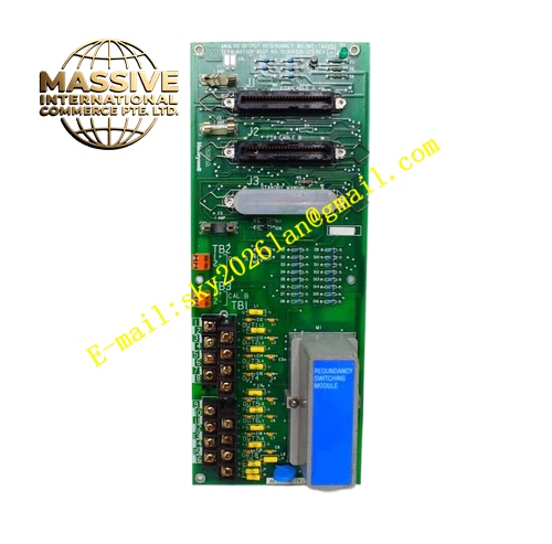
Description
HONEYWELL MC-TPIX52
Technical Specifications Backplane bus power supply; Multi-channel high level pulse input; Accept pulse amplitude from 3.5V to 30V; Wide frequency measurement range; Hardware edge detection circuit; Channel surge protection; Rack plug-in design, matched with 51304084 series FTA terminal block.
Functional Features Acquire high-level pulse signals from turbine flow meters, rotary speed pickups and pulse output sensors; Compute instantaneous frequency and accumulated pulse total; Detect pulse signal dropout and abnormal signal amplitude; Isolate each input channel to reduce cross-channel interference; Transmit process measurement and fault status to controller; Support high-resolution event time stamping for sequence recording.
Application Scenarios Oil & gas and chemical plant DCS cabinets; Flow metering and totalization for pipeline media; Rotational speed monitoring for compressors, fans and agitators; Batch counting and material transfer measurement.
Performance Parameters Operating temperature range 0℃ to 60℃; Relative humidity 5% to 95%, non-condensing; Stable frequency measurement accuracy; Comply with industrial EMC standards for control cabinet environment.
Material Composition FR-4 multilayer printed circuit board; Gold-plated backplane gold finger connectors; High-speed pulse counting chips; Surge absorption components; Precision filter resistors and capacitors; Anti-static flame retardant plastic front panel.
Structural Features Rack plug-in card structure; Front panel equipped with LED indicators for module running and channel status; Rear gold fingers connect rack backplane bus; Anti-reverse insertion positioning notch; Model marking printed on card surface; Matching FTA terminal assembly for field wiring termination.
Working Principle High-level pulse signal from field sensor passes through FTA terminal assembly and enters the module. Internal hardware circuit detects rising or falling edge of pulse signal. High-speed counter accumulates pulse quantity and calculates frequency value. Digital measurement data is sent to controller via I/O Link bus. Diagnostic circuit continuously monitors signal amplitude and pulse presence, and sends fault alarm when signal disappears or exceeds normal range.
Installation Requirements Wear anti-static wrist strap during installation and removal; Insert card fully into rack slot and tighten fixing screw; Install matched FTA terminal assembly and complete field wiring termination; Cabinet protective ground must be qualified; Separate pulse signal cable and high-power cable routing; Verify hardware version compatibility with controller firmware.
Precautions for Use Prohibit hot swapping of module; Do not connect high voltage AC signal to pulse input channels; Inspect FTA terminal screw tightness periodically; Check field pulse sensor and wiring when channel fault alarm triggers; Confirm matching FTA part number before commissioning.







