



Description
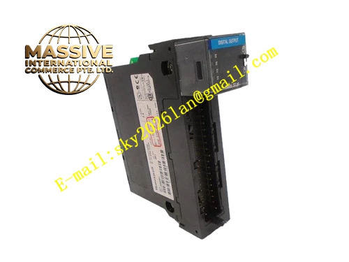
Honeywell TC-ODD321
Technical Specifications
- Channel Count: 32 digital output channels
- Output Type: Sinking open collector transistor output
- Rated Load Voltage: 24V DC
- Single Channel Max Continuous Current: 150mA
- Channel Isolation: Group-wise optocoupler isolation, 500V AC isolation voltage
- Operating Temperature: 0°C to +60°C
- Backplane Bus: Honeywell TC series DCS rack backplane
- Power Consumption: 7W maximum with all channels loaded
Functional Features Each channel independent electronic overcurrent limiting protection. Output status readback for command feedback comparison. Group fault diagnosis for power supply and communication status. Front panel LED indication for module power and group fault. Backplane communication with CRC checksum for output command frames. Output hold state when backplane communication loss occurs.
Application Scenarios DCS system auxiliary valve solenoid control Local panel alarm light and annunciator drive Pump and fan auxiliary relay control output Batch process sequence control discrete output TC series DCS rack spare replacement and I/O expansion
Performance Parameters
- Output switching time: ≤1ms
- Overcurrent protection action time: <2µs
- Group channel crosstalk: -60dB minimum
- Diagnostic coverage for short circuit and overload fault
Material Composition FR4 UL94 V0 multilayer PCB, power NPN transistor switches, high speed optocoupler isolation chips, current sampling resistors, TVS surge diodes, X7R ceramic decoupling capacitors, removable screw terminal block, black flame retardant plastic module housing, gold plated backplane edge connector.
Structural Features Standard plug-in rack card compatible with TC series DCS rack slot. Split removable terminal block for 32 channel field wiring. Front panel LED indicators for module power and group fault alarm. Internal isolation barrier divides backplane logic zone and field output power zone. Card edge anti-reverse keying structure.
Working Principle DCS controller sends digital output command via rack backplane bus. Onboard logic chip validates command CRC checksum. Valid command drives optocoupler isolation stage and turns on corresponding output transistor. Sampling resistor monitors channel current continuously. If load current exceeds threshold, hardware current limit circuit activates and fault flag is sent back to controller. When communication from controller stops, output channels maintain last commanded state.
Installation Requirements Power off rack before inserting or removing module. Field wiring uses twisted pair cable, separate from analog signal cable and power cable. Inductive loads must install freewheeling diode directly across load terminals. Tighten terminal screws to specified torque value. Confirm controller firmware version compatibility before commissioning.
Usage Notes Overcurrent fault latches channel off, rack power cycle required to reset fault after field repair. Do not connect load current exceeding 150mA per single channel. Maintain cabinet ventilation airflow to prevent overheating at high channel loading condition. No internal circuit component modification is allowed.







