



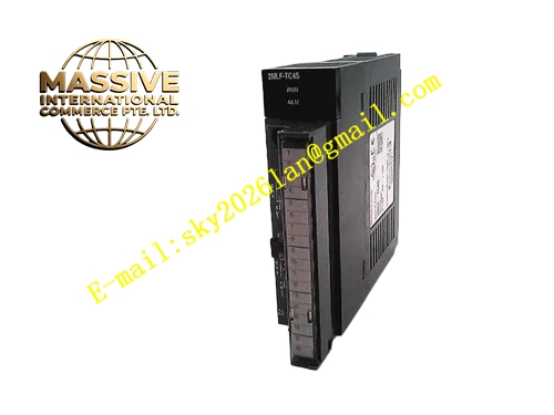
Description
Honeywell TC-PCICO2
Technical Specifications
- Compatible device: C200 controller
- Network interface: 1 RJ45 redundant control network port
- Communication rate: 100 Mbps auto-negotiation
- Network protocol: Honeywell C200 control network proprietary protocol
- Supported node capacity: 64 network nodes per card
- Supply power: 5 V DC from controller backplane
- Operating temperature: 0 °C to +60 °C
- Isolation withstand voltage: 1500 VAC
Functional Features RJ45 interface connects to cabinet control ring network via shielded cable. On-board PHY chip auto-negotiates network speed and duplex mode. Network cable disconnection and collision fault real-time diagnosis, triggers communication alarm. On-board LEDs indicate network link and data transmit/receive activity. All transmitted data frames carry CRC checksum, ensures accurate communication with upper stations. Supports online reading of network diagnostic data for ring network troubleshooting.
Application Scenarios Communication connection between C200 controllers and upper operator stations Ring network access for small-to-medium C200 control systems Spare part replacement for legacy control card communication faults Network assembly for new production line C200 installations
Performance Parameters
- Network latency: ≤1 ms
- Maximum cable transmission distance: 100 meters Cat5e shielded cable
- ESD protection: ±8 kV contact discharge
- Fault detection response: ≤100 ms
- Mean time between failures: 400,000 hours
Material Composition FR4 PCB substrate Ethernet PHY transceiver chip Network isolation transformer TVS surge protection diodes Gold-plated RJ45 connector Gold-plated backplane edge fingers
Structural Features Standard Eurocard dimensions, inserts into the controller communication slot. Front panel RJ45 interface, with LINK and ACT LEDs positioned adjacent to the port. Metal shielded front panel isolates high-speed network signals. Differential traces are impedance-controlled to 100 Ω for network characteristic impedance matching.
Working Principle After insertion into the backplane, the card initializes Ethernet communication logic, establishing connections with other nodes on the ring network. Process data and alarm information to be uploaded to the operator station are sent over the RJ45 interface to the ring network. Setpoints and operation commands from upper stations travel over the ring network to the card, then stored in controller registers. The PHY chip continuously monitors cable connection status; cable disconnection triggers network fault alarm. Data frames pass CRC verification, corrupted data triggers automatic retransmission.
Installation Requirements Use Cat5e shielded cable to connect the card RJ45 port to the ring network switch. Single-point shield grounding for cable shields. Set network node address in controller configuration software after power-up. Route network cables separately from high-voltage power cable trays. Verify LINK LED is solid on and ACT LED blinks after power-up, confirming normal network connection.
Usage Notes Network wiring routed in the same tray as power cables causes electromagnetic interference and packet loss. Broken connector latch causes cable loosening; inspect connector lock status regularly. Node address must not conflict with other devices on the ring network; address collision causes entire ring network communication failure.







