



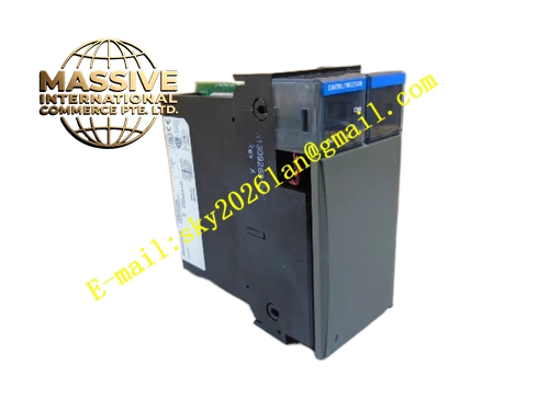
Description
Honeywell TC-PRS021
Technical Specifications
- Input voltage: 20–30 V DC wide-range DC input
- Rated output: 5 V DC, 8 A continuous current for backplane logic supply
- Regulation accuracy: ±1%
- Redundancy function: Dual-board parallel current sharing, current imbalance ≤5%
- Operating temperature: 0 °C to +60 °C
- Isolation withstand voltage: 1500 VAC for 1 minute
- On-board protection: Overvoltage, overcurrent, reverse polarity protection
Functional Features Wide voltage input accommodates industrial field grid fluctuation conditions. Dual-board parallel automatic current sharing, output load evenly distributed between two power boards. Reverse polarity protection, blocks power flow if supply is reversed, prevents downstream load damage. On-board LEDs indicate power output normal and fault alarm status. Output EMI filtering removes high-frequency ripple that would interfere with controller logic circuits. Hot swap compatible, faulty board replaced online without interrupting system operation.
Application Scenarios Cabinet internal logic supply unit for C200 controllers Redundancy power configuration for high-availability control systems Spare part replacement for output drift and excessive ripple in legacy power boards Power circuit assembly for new C200 cabinets Power reliability upgrade for unmanned remote station controllers
Performance Parameters
- Output ripple: ≤30 mV peak to peak
- Overvoltage protection threshold: 5.7 V DC
- Overcurrent protection threshold: 9 A
- Power switchover time: ≤1 ms, no perceptible disturbance to loads
- Conversion efficiency: 90% at full load
Material Composition FR4 flame retardant PCB substrate DC-DC regulator power chip Output filter capacitor bank Current sharing diodes TVS surge suppression diodes Gold-plated backplane edge fingers Metal shielded heat dissipation enclosure
Structural Features Standard Eurocard dimensions, inserts into the dedicated power slot in the C200 cabinet. Front panel houses power switch, status LEDs and fault alarm contacts. Metal enclosure integrates cooling fins, assisting heat dissipation for power components. Input and output wiring terminals are zoned, separating high-current and low-voltage areas. Anti-keying rail structure prevents insertion into signal I/O slots.
Working Principle External 24 V DC power connects to the regulation board, passes through reverse polarity protection circuit and EMI filter before entering the DC-DC regulator, converting to stable 5 V DC output for the controller backplane. When two boards run in parallel, the current sharing circuit automatically balances output current between units, imbalance held within 5%. Output voltage is continuously sampled by the feedback circuit, adjusting regulator duty cycle to maintain output accuracy. Overvoltage, overcurrent and internal temperature monitoring circuits shut down output and trigger a fault flag when parameters exceed safe limits.
Installation Requirements Insert the board into the dedicated power slot only when rack power is off, press evenly until gold fingers are fully seated. Connect 24 V DC input strictly per silk-screen polarity marking. For redundant configuration, install two power boards in adjacent slots, connect current-sharing cables. Measure output voltage after power-up, confirm regulation accuracy holds 5 V ± 0.05 V. Connect grounding terminal reliably to cabinet protective ground.
Usage Notes Total backplane load current must not exceed the 8 A rating of a single power board; overload triggers over-temperature protection. When replacing a faulty power board, confirm the other redundant unit is carrying full load without alarm before hot swap. Never block heat sink ventilation with cabling; poor ventilation shortens power supply service life. Never short-circuit output terminals; short circuit instantly destroys the regulator power chip.







