Description
ICS Triplex T3485
Technical Specifications & Performance Parameters:
- Power Supply: 20 V DC ~ 32 V DC backplane power feeding, nominal 24 V DC
- Channel Configuration: 4 analog input channels, 4 analog output channels, 8 digital input channels, 8 digital output channels
- Analog Input Ranges: 0‑10 V, ±10 V, 4‑20 mA
- Analog Output Ranges: 0‑20 mA, 4‑20 mA
- Digital Input Signal: 24 V DC discrete input
- Digital Output Signal: 24 V DC discrete output, per‑channel 0.5 A maximum drive
- Analog Measurement Accuracy: ±0.1 % full scale
- Operating Temperature: ‑40 °C ~ +70 °C
- Storage Temperature: ‑40 °C ~ +85 °C
- Safety Certification: TÜV IEC 61508 SIL 3
- Maximum Power Consumption: 21 W
- Weight: 1.14 kg
- Form Factor: Standard Regent‑Plus rack plug‑in module
Functional Features:
- Full TMR triple‑redundant circuit for every input and output channel, implement 2‑out‑of‑3 hardware voting
- Multi‑type mixed‑signal processing capability inside single module slot, save rack slot resources
- Complete channel‑level diagnostics for analog loops and digital circuits, detect wiring fault and internal hardware anomaly
- Hot‑swap support for online module replacement
- Configurable fail‑safe state for analog‑output and digital‑output channels under fault condition
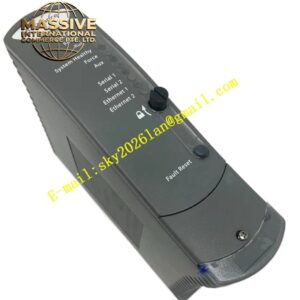
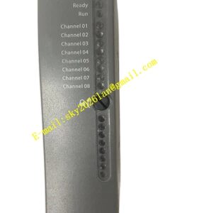
- Front‑panel LED indicator group for each channel type, show running status and fault‑alarm information
- Timestamped all‑channel fault‑event upload to system fault historian
- Galvanic isolation between all field‑signal circuits and internal safety backplane bus
Working Principle: Field analog and digital signals enter respective channel circuits. Each channel processes signal via three independent redundant sub‑circuits. Hardware voting circuits validate input measurement results and output command states. Analog‑input signals convert into digital data for processor logic calculation; digital‑input status transmits to safety processor. Safety‑processor control commands go through voting and drive analog‑output and digital‑output field channels. Built‑in diagnostic circuit monitors all channel loop status continuously. Fault events get timestamped and uploaded to system historian, faulty sub‑circuit gets isolated automatically without affecting overall channel function.
Material Composition & Structural Characteristics:
- Housing: Die‑cast aluminum alloy anti‑interference shielding shell
- Circuit substrate: Multi‑layer FR‑4 industrial printed circuit board, integrate multi‑type signal conversion and drive components
- Connectors: Gold‑plated backplane connector and multi‑group high‑density field‑wiring terminal blocks
- Front panel: Flame‑retardant PC engineering plastic with multi‑group LED indicator arrays, IP20 protection grade
- Plug‑in card‑type rack‑slot structure
Installation Requirements:
- Install module into mixed‑signal dedicated slot of Regent‑Plus rack chassis, fasten front‑panel locking screws
- Different‑type field‑signal cables implement separated routing, all adopt shielded twisted‑pair cables
- All cable shielding layers single‑end grounded at cabinet ground bus‑bar
- Cabinet protective ground resistance ≤4 Ω
- Maintain good cabinet ventilation heat‑dissipation performance
- Field‑side actuator and sensor load parameters must strictly match respective channel‑specification limits
Application Scenarios:
- Small‑scale local safety‑interlock subsystems for petrochemical plants
- Skid‑mounted equipment integrated safety‑instrumented‑system control
- Chemical‑plant auxiliary unit compact safety‑control cabinets
- Power‑plant local auxiliary‑equipment safety‑interlock
- Compact‑size fire‑gas monitoring and safety‑actuation combined control units
Usage Notes:
- Hot‑swap operation only permitted under normal system health status
- Module shell disassembly is forbidden; zero user‑serviceable internal parts
- Strictly separate different‑signal‑type field wiring to avoid signal cross‑interference
- After module replacement, complete verification for all input‑output channel types and diagnostic functions
- Operate strictly within rated operating temperature range
- Periodically inspect all field‑cable insulation and terminal‑connection tightness