Description
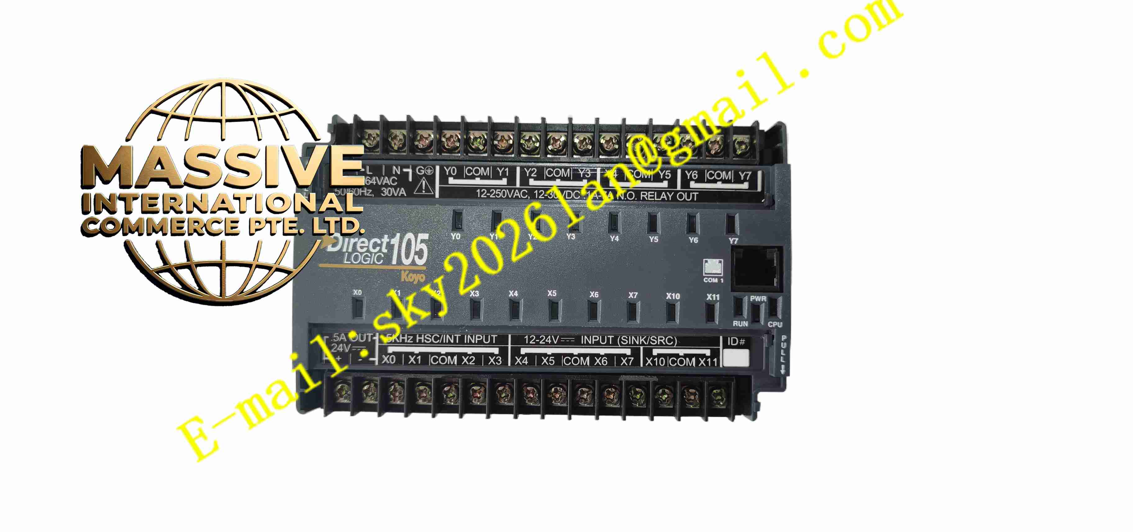
Koyo F1-130DR
Technical Specifications
- Product Type: Integrated PLC with relay outputs
- Total I/O Count: 30 points, 16 digital inputs, 14 relay digital outputs
- Input Signal: 24VDC sink/source digital input
- Output Type: Mechanical relay contact output
- Relay Contact Rating: 2A per point, 8A common point
- Program Memory: 2K steps ladder program memory
- Data Memory: Retentive memory for holding registers
- Communication Port: RS485 serial port for programming and host communication
- Power Supply: 100-240VAC mains supply
- Protection Rating: IP20
- Operating Temperature: 0 °C to +60 °C
Functional Features
- All-in-one compact design combining CPU, power supply and I/O in single unit.
- Relay output channels support switching of AC and DC low power loads.
- Built-in high speed counter function for pulse signal acquisition from encoders.
- Timer and counter instructions for sequence and timing control.
- Retentive data memory preserves register values during power outage.
- RS485 port supports program upload/download and Modbus communication.
- LED indicators for each input and output channel status.
- Built-in watchdog timer triggers safe output state when program execution fails.
- Ladder diagram programming compatible with Koyo programming software.
- Expandable I/O bus to connect external expansion modules for larger I/O demand.
Application Scenarios
- Small automatic conveyor control
- Packaging machine sequence control
- Material handling and sorting equipment
- Small pump and valve interlock control
- Workshop auxiliary machine automation
Material Composition
- Housing: Flame-retardant ABS plastic casing
- Main PCB: FR4 printed circuit board
- Input circuit: Optocoupler isolation chips
- Output elements: Sealed mechanical signal relays
- Terminal block: Copper alloy screw terminals
- Status indicators: High brightness LED diodes
Structural Characteristics
- Rectangular compact DIN rail mounting housing.
- Front panel contains channel LED indicators and status LEDs.
- Upper terminal block for mains power supply and digital input wiring.
- Lower terminal block for relay output field wiring.
- Rear side spring clip for DIN rail fixing.
- Internal optocoupler separates field input circuit and internal logic circuit.
Working Principle After power on, the PLC executes ladder program in cyclic scan mode. It reads the status of all digital input terminals via optocoupler isolation circuit. The CPU processes logic operations according to user ladder program. When logic result activates output point, the corresponding relay coil energizes and closes relay contact to drive field load. Watchdog circuit monitors program scan cycle continuously. If program stops executing, watchdog forces all outputs to safe state. RS485 port exchanges program and data with programming software or upper host system.
Installation Requirements
- Mount unit horizontally on standard DIN rail inside control cabinet.
- Maintain side clearance for heat dissipation.
- Separate input signal wiring from high power output wiring.
- Use appropriate wire gauge for relay output load wiring.
- Tighten terminal screws to specified torque.
- Download ladder program and perform offline simulation before field test.
- Test each I/O channel manually after installation.
Usage Notes
- Do not exceed relay contact rated voltage and current.
- Add surge suppression components for inductive loads connected to relay outputs.
- Keep cabinet dry and free of conductive dust.
- Backup program file before firmware modification.
- Replace unit if relay contacts show burning or sticking.
- Disconnect power before removing PLC from DIN rail.
- Check terminal screw tightness regularly under vibrating environment.