Description
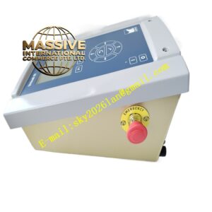
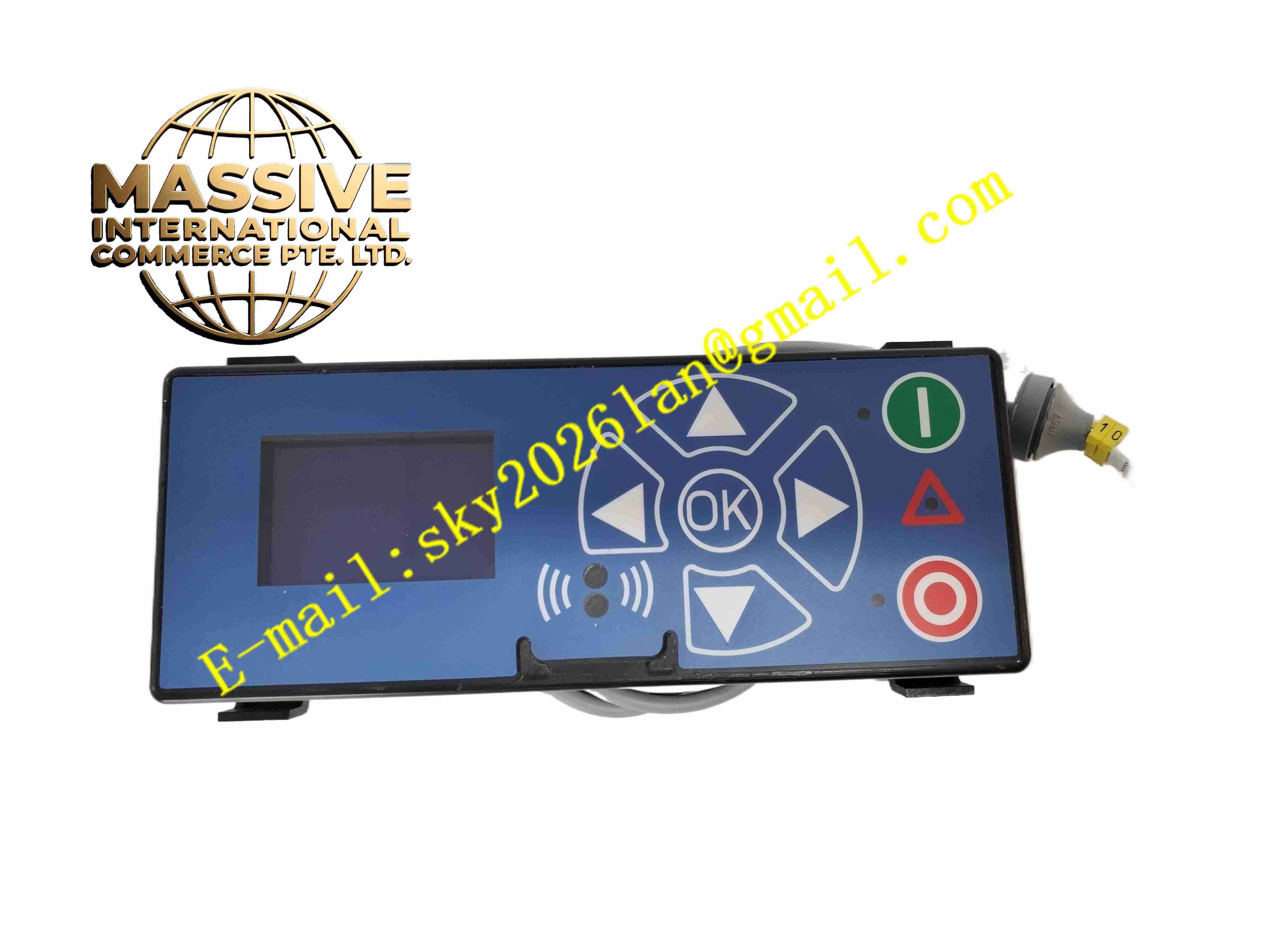
Lenze ESMD113L4TXH509
Technical Specifications
- Product Type: AC frequency inverter
- Input Power: 3-phase 400V AC
- Rated Power: 11 kW
- Output Frequency Range: 0 Hz to 500 Hz
- Control Mode: V/F control, vector speed control
- Communication Interfaces: Modbus RTU, CANopen, optional Profibus DP
- Digital Inputs: 6 programmable digital inputs
- Digital Outputs: 2 relay digital outputs
- Analog I/O: 1 analog input, 1 analog output
- Protection Rating: IP20
- Operating Temperature: -10 °C to +50 °C
- Certifications: CE, UL, RoHS
Functional Features
- Compact cabinet-saving design for standard control cabinet installation.
- Built-in motor overload, overcurrent, overvoltage, undervoltage and over-temperature protection.
- Adjustable acceleration and deceleration ramps to reduce mechanical shock during motor start and stop.
- Integrated PID closed-loop function for pressure, flow and temperature automatic regulation.
- Parameter copy function via optional keypad for fast batch commissioning of multiple drives.
- Free programmable digital and analog terminals for flexible logic configuration.
- Integrated braking transistor to connect external braking resistor for fast stop applications.
- Built-in EMC filter option to suppress conducted electromagnetic interference.
- Fault memory stores the last 10 fault records with timestamp for troubleshooting.
- Sleep and wake-up function for pump and fan energy saving operation.
Application Scenarios
- Conveyor belt speed control in material handling systems
- Centrifugal fan and water pump variable speed energy saving control
- Packaging machine main drive control
- Textile machinery and printing equipment motor regulation
- Woodworking and plastic processing machinery speed control
Material Composition
- Housing: Flame-retardant thermoplastic plastic casing
- Main PCB: FR4 high temperature printed circuit board with conformal coating
- Power stage: IGBT power modules, high frequency rectifier bridge
- Heat sink: Aluminum alloy extruded heat sink
- Terminal block: Copper alloy screw terminals for power and signal wiring
- Cooling fan: Brushless DC cooling fan for forced air cooling
Structural Characteristics
- Vertical rectangular modular structure for DIN rail mounting.
- Front panel with removable local keypad interface and status LED indicators.
- Upper section contains three-phase mains input and motor output power terminals.
- Lower section houses control signal terminals for sensor and PLC wiring.
- Internal layout separates high voltage power circuit and low voltage control circuit.
- Aluminum heat sink sits on the rear side for heat dissipation.
Working Principle Three-phase AC mains power enters the internal rectifier circuit and converts to DC bus voltage. The IGBT inverter bridge converts DC voltage back to three-phase AC with adjustable voltage and frequency. The control board samples output current and voltage continuously, adjusts IGBT switching state according to setpoint and feedback signal to change motor speed and torque. Built-in protection circuits monitor internal temperature, current and bus voltage. The drive triggers shutdown and fault alarm when parameters exceed safe thresholds.
Installation Requirements
- Mount vertically on standard DIN rail inside dust-free control cabinet.
- Maintain specified vertical clearance above and below the unit for airflow.
- Use shielded twisted pair cable for motor wiring, keep motor cable separated from signal cables.
- Complete protective earth connection with low resistance earth wire.
- Set motor rated parameters including rated current and rated speed during commissioning.
- Perform auto motor tuning to optimize control performance.
- Verify all protection setpoints before putting drive into automatic operation.
Usage Notes
- Do not apply input voltage exceeding rated specification.
- Do not touch internal power components for 10 minutes after power cut, DC bus retains residual high voltage.
- Keep cabinet free of corrosive gas, oil mist and conductive dust.
- Check cooling fan operation regularly during long-term continuous operation.
- Use insulated tools for power terminal wiring work.
- Backup parameter set before firmware upgrade or parameter modification.
- Replace damaged fan immediately if fan failure alarm activates.