Description
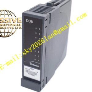
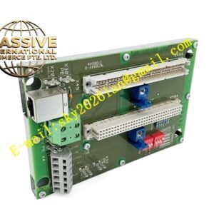
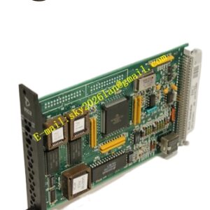
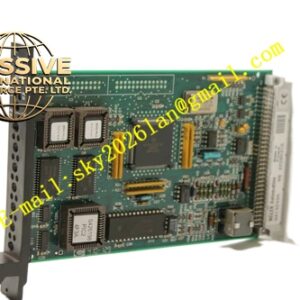
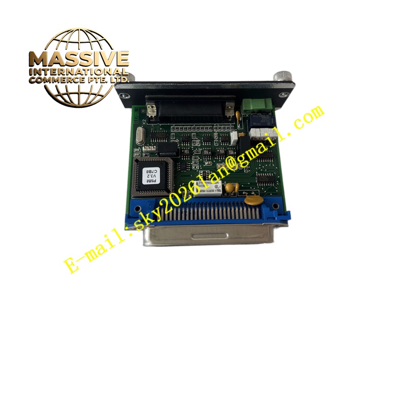
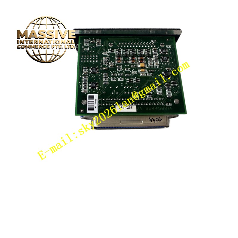
Metso D200175L
Technical Specifications Power supply 24 V DC from rack backplane; typical operating current 200 mA; Modbus RTU serial communication interface; operating temperature -20 ℃ to +70 ℃; PCB conformal coating; rack plug-in design for Metso MAX rack; front panel communication activity LEDs; galvanic isolation between rack internal bus and field serial lines.
Functional Features Modbus RTU master or slave configurable through software; hardware isolation protects rack backplane from field ground potential difference; real-time serial data buffering; communication error detection including parity and framing error; front panel transmit and receive activity indication; non-volatile memory stores station address and baud rate configuration.
Application Scenarios Mining flotation plant remote instrument communication, pulp mill field transmitter data collection, mineral processing supervisory data link, wastewater treatment plant Modbus instrument networking.
Material Composition Flame-retardant plastic module casing; FR4 signal PCB with acrylic conformal coating; isolated serial transceiver chips; gold-plated rack backplane edge connector; front panel LED light pipes; screw terminal blocks for field serial wiring.
Structural Characteristics Horizontal rack plug-in form factor; front panel carries communication status LEDs and field signal terminal block; rear gold finger connects to Metso MAX internal rack bus; isolation circuit separates control rack digital ground and field instrument signal ground.
Working Principle Module receives data packets from rack CPU over backplane bus. Protocol controller formats data into Modbus RTU frames and transmits to field instruments over serial line. Received serial field data is validated, buffered and forwarded to rack CPU. Isolation circuit blocks ground loop current between control cabinet and field instrument location.
Installation Requirements Insert module into de-energised Metso MAX rack slot; set Modbus station address and baud rate via configuration software; use shielded twisted pair cable for field Modbus wiring; install bus terminating resistor at physical bus endpoints; single-point ground cable shield inside control cabinet.
Operation Notes Back up communication configuration before module replacement; verify wiring polarity of RS485 differential lines; avoid scraping conformal coating during module extraction; check LED activity to diagnose communication link failure.