Description
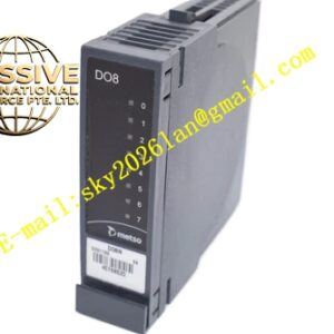
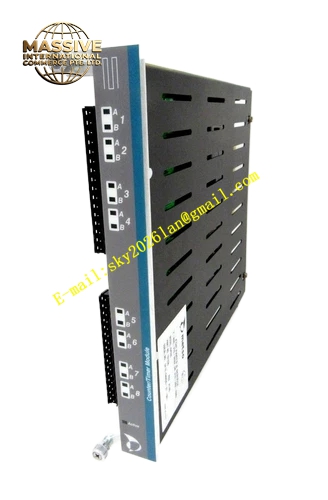
METSO IOP335
Technical Specifications: System power supply 24 VDC from rack backplane; maximum input pulse frequency 50 kHz; counting range 0‑999 999 999; timing resolution 0.1 ms; 4‑channel pulse input, 2‑channel relay output; input signal compatible with NPN, PNP pulse signal; relay contact rated load 250 VAC 2 A; field‑to‑logic circuit galvanic isolation 1500 VAC; rack plug‑in installation; operating temperature range ‑20 ℃‑+55 ℃; storage temperature ‑40 ℃‑+85 ℃; protection class IP20; module weight 0.58 kg.
Functional Features: Multi‑channel independent high‑speed pulse counting; frequency and period measurement function; programmable timing and delay trigger; hardware pulse anti‑jitter filtering; relay contact output for threshold trigger; module self‑diagnosis; open‑circuit and abnormal pulse detection; fault alarm upload to DCS host system; support counter value reset via system command; single‑channel fault will not affect other channel operation.
Application Scenarios: Pulp and paper mill production line speed measurement and length counting cabinet; thermal power plant coal feeder pulse totalizing control cabinet; chemical plant flow pulse accumulation monitoring cabinet; mining conveyor speed monitoring control cabinet; manufacturing equipment pulse position feedback control cabinet.
Performance Parameters: Counting accuracy ±0.01 %; pulse signal response time less than 1 ms; strong anti‑electromagnetic‑interference performance complying with IEC61000 standards; support 7×24 hours continuous full‑load operation; stable counting performance under long‑distance field wiring condition.
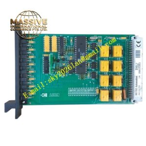
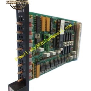
Material Composition: Fiberglass epoxy multilayer printed circuit board; high‑speed pulse processing chip; optoelectronic isolation components; industrial‑grade signal filtering capacitor; gold‑plated backplane edge connector; metal front baffle; circuit‑board surface coated with three‑proof conformal coating.
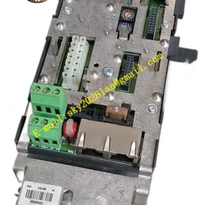
Structural Features: Standard rack plug‑in card‑type structure; front panel integrated LED indicators for power supply, running status and each channel fault; rear gold‑plated connector mates with rack backplane bus; internal high‑speed signal circuit and power circuit implement physical separation; mechanical anti‑loose locking buckle equipped on front panel to prevent loosening caused by equipment vibration.
Working Principle: Field pulse sensor signals enter IOP335 module through matched terminal base. Isolation and filtering circuit eliminate interference noise of pulse signal. Internal high‑speed chip completes counting, frequency calculation and timing processing. Processed numerical value transmits to DPU controller via backplane bus. When counting value reaches preset threshold, relay output channel acts and sends trigger signal to field equipment. Module monitors input signal status all the time and uploads fault information once abnormality occurs.
Installation Requirements: Insert IOP335 module into designated dedicated slot of MaxDNA I/O rack and match with original supporting terminal base. Adopt shielded twisted‑pair cables for pulse signal wiring. Signal cables and high‑power motor cables are laid in separate cable trunking. Cabinet protective grounding terminal must realize reliable connection. Reserve 20 mm‑30 mm ventilation clearance around module for heat dissipation.
Precautions for Use: Cut off rack backplane power supply before plugging and removing module. Wear anti‑static wrist strap when touching internal circuit‑board components. Input pulse amplitude must match module specification, prohibit input of over‑voltage signal. Inspect wiring terminal tightness periodically. Prevent conductive dust accumulation inside rack. Avoid condensation inside control cabinet.