Description
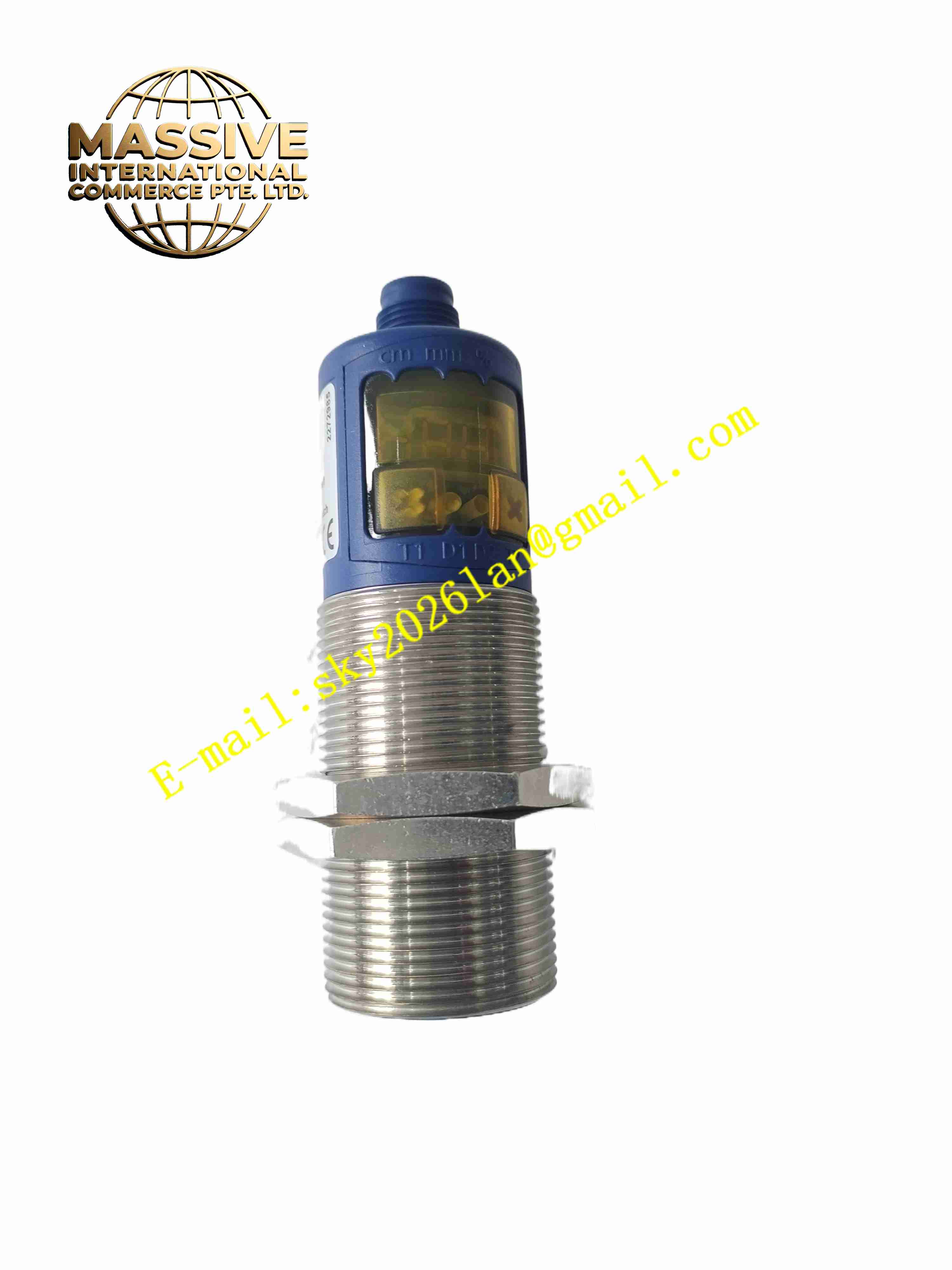
microsonic MIC+130IUTC
Technical Specifications Measuring blind zone 200 mm; effective measuring range 200 mm to 1300 mm; maximum detection limit 2000 mm; ultrasonic transducer frequency 200 kHz; supply voltage 9 VDC to 30 VDC; analog output 4-20 mA / 0-10 V switchable; one push-pull switching output compatible with PNP and NPN; 5-pin M12 circular connector; IP67 protection rating.
Functional Features Built-in temperature drift compensation to stabilize measurement accuracy; analog output rising/falling characteristic configurable via teach-in button; short-circuit protection for analog and switching output; synchronous function allows up to 10 sensors working together without mutual interference; LED digital display shows measured distance value; IO-Link interface for remote parameter configuration and diagnostic data upload; reverse polarity power protection.
Application Scenarios Bulk material silo level monitoring; conveyor belt object detection; packaging machine material distance measurement; warehouse stack height detection; mobile agricultural machinery distance control.
Performance Parameters Operating ambient temperature -25℃ to +70℃; storage temperature -40℃ to +85℃; relative humidity 5% to 95%, no condensation; repeat accuracy ±0.15%; measurement accuracy ±1% full scale; resolution ranges from 0.18 mm to 0.57 mm.
Material Composition Nickel-plated brass threaded M30 housing; PBT plastic internal structural components; polyurethane foam ultrasonic transducer face; glass filled epoxy encapsulation for ultrasonic chip; TPU cable sealing parts; polycarbonate LED display window.
Structural Characteristics Cylindrical M30 threaded body for standard nut mounting; front ultrasonic transducer emission window; front panel with teach-in buttons and digital LED display; side M12 5-pin connector for power and signal wiring; fully sealed internal cavity to meet IP67 protection.
Working Principle Sensor transducer emits ultrasonic sound wave. Sound wave travels through air, reflects off target surface and returns back to transducer. Sensor circuit calculates distance by measuring sound wave round-trip time. Internal temperature compensation algorithm corrects sound velocity deviation caused by temperature change. Measured distance value converts into analog 4-20mA or 0-10V signal and switching output for control system.
Installation Requirements Install sensor with M30 mounting nut, reserve proper blind zone space between sensor and target surface. Route M12 connecting cable away from high-voltage power cable. Set measuring window and switch threshold through teach-in operation after power supply. Configure multi-sensor synchronous mode when multiple ultrasonic sensors installed closely.
Usage Notes Avoid strong air flow directly blowing onto ultrasonic transducer face. Prevent heavy dust and sticky material accumulation on transducer surface. Do not expose sensor to strong corrosive gas environment. Verify target surface reflectivity before final installation.