Description
Mitsubishi MR-S11-200-Z37
Technical Specifications Single axis servo amplifier; 200V AC single-phase or three-phase input; rated power 2kW; pulse/direction analog command interface; incremental encoder feedback input; built-in dynamic brake circuit; over-current, over-voltage, under-voltage, over-temperature and overload protection; panel mounting or DIN rail mounting; IP20 protection rating.
Functional Features Closed-loop position, speed and torque control for servo motor; dynamic brake function for rapid motor stop; multi-level hardware fault protection; non-volatile memory for saving motor parameters and gain settings; fault history recording; analog monitor output for speed and torque observation; pulse command input compatible with host motion controller.
Application Scenarios Traditional CNC machine tool feed axis; older generation packaging machinery servo axis; textile machine positioning drive; material cutting special machine; automated assembly retrofitting project.
Performance Parameters Operating ambient temperature 0℃ to +55℃; storage temperature -40℃ to +85℃; relative humidity 5% to 90%, no condensation; comply with IEC industrial EMC standard.
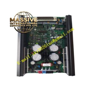
Material Composition Metal alloy housing with integrated heat sink; multi-layer power PCB; IGBT power module; DSP motion control chip; current sampling sensors; filter electrolytic capacitors; screw terminals for power, motor and signal wiring.
Structural Characteristics Vertical compact module structure; power terminals on lower section, encoder and control signal terminals on upper section; internal separation layout between high-power power circuit and low-voltage signal circuit; rear heat sink for natural convection heat dissipation.
Working Principle AC input power rectifies to DC bus voltage inside servo amplifier. DSP chip receives motion command signal from upper controller, generates PWM pulse signal to drive IGBT module, and outputs variable frequency three-phase AC power to servo motor. Encoder feedback signal transmits back to drive, completing closed-loop speed and position regulation. Protection circuit continuously monitors operating state and cuts off torque output once fault condition triggers. Dynamic brake circuit consumes motor inertia energy for fast deceleration.
Installation Requirements Mount servo amplifier inside control cabinet on DIN rail or mounting plate. Use shielded cable for motor power and encoder wiring, separate power cable and signal cable routing. Complete reliable protective earthing. After power-on, perform motor parameter setting and auto-tuning of servo gain. Test dynamic brake function.
Usage Notes Wait for DC bus capacitor full discharge before disconnecting wiring. Clean heat sink dust periodically. Backup servo parameters before module replacement. Do not operate drive without matched servo motor.