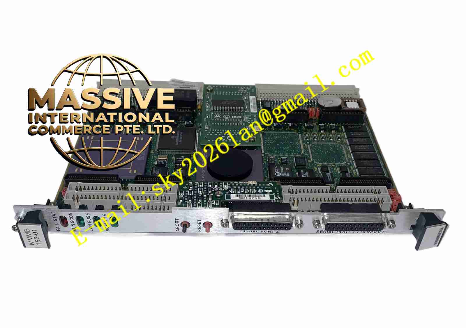

Description
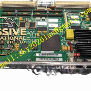
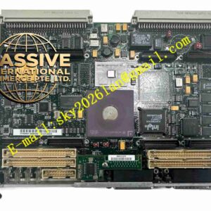
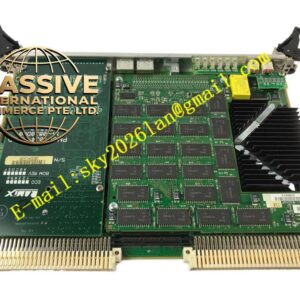
Motorola MVME162-813
Technical Specifications
- Processor: 32 MHz enhanced 32-bit microprocessor.
- Memory: 8MB standard DRAM.
- Bus Interface: VMEbus interface supporting A24/A32 addressing and D8/D16/D32 data transfers.
- System Control: VMEbus system controller with Global Control and Status Register (GCSR).
Functional Features
- Large Memory Capacity: 8MB DRAM provides ample space for complex Real-Time Operating Systems (RTOS) like VxWorks or pSOS.
- Flexible Addressing: Supports A16/A24/A32 address mapping from the local bus to the VMEbus.
- Debug Support: Onboard 162Bug debug monitor firmware simplifies system boot and low-level development.
- High Expandability: IndustryPack module support adapts to diverse field I/O requirements.
Application Scenarios
Distributed Control Systems (DCS), Programmable Logic Controller (PLC) core processing units, large-scale test equipment, and communication base station control nodes.
Performance Parameters
- Power Requirements: +5V at 3.5A typical, 4.5A max; +12V and -12V at 100mA max.
- Operating Environment: 0°C to 70°C with forced-air cooling; storage temperature -40°C to +85°C.
- Humidity Tolerance: 5% to 90% non-condensing.
Material Composition
Flame-retardant FR-4 industrial PCB, Motorola MC68040 series processors, high-speed DRAM chips, and custom ASICs.
Structural Characteristics
Standard 6U VME Eurocard design. Front panel features eight status LEDs (including RUN, FAIL, STAT) and ABORT/RESET physical buttons.
Working Principle
The MC68040 processor acts as the core, communicating with the MCchip ASIC via the local bus. The MCchip manages serial ports, LAN, SCSI, and DRAM parity. The VMEchip2 handles DMA and interrupt requests from the external VME backplane for efficient parallel processing.
Installation Requirements
- Ensure VME chassis card guides are intact; push the board in smoothly to prevent backplane connector pin bending.
- Configure hardware jumpers correctly (e.g., VME system controller, memory size).
- Maintain an unobstructed cooling airflow path.
Usage Precautions
- Monitor front-panel LEDs; if the FAIL light is on, read the error code via 162Bug.
- Avoid exposing unshielded interfaces to strong electromagnetic interference.
- Strictly follow official guidelines during firmware upgrades to prevent system bricking.