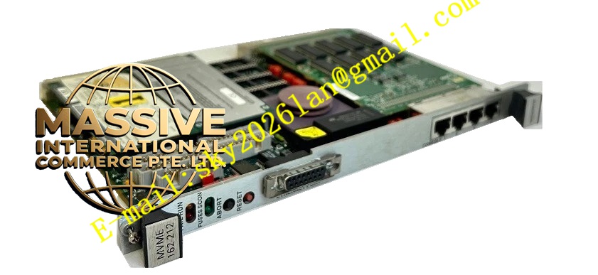
Description
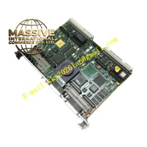
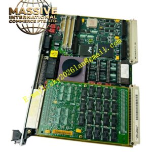
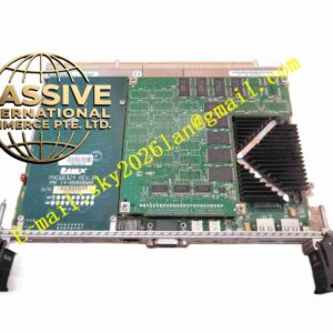
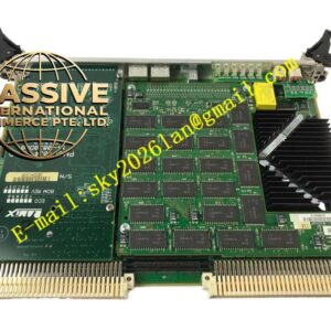
Motorola MVME162P-244L
Technical Specifications
- Microprocessor: 25 MHz MC68LC040 enhanced 32-bit microprocessor (includes 8KB cache and MMU, without FPU).
- Main Memory: 16MB Synchronous Dynamic Random Access Memory (SDRAM).
- Non-Volatile Storage: 512KB battery-backed SRAM, 1MB Flash memory, and 8K x 8 NVRAM with a battery-backed real-time clock.
- Bus Interface: A32/D64 VMEbus master/slave interface with full system controller functionality.
Functional Features
- Petra ASIC Integration: Replaces previous MC2, IP2, and MCECC chips, optimizing local bus memory burst cycles and VMEbus D64 block transfers.
- IndustryPack Expansion: Supports up to four 16-bit or two 32-bit IndustryPack (IP) ports, providing flexible I/O expansion.
- Serial Communications: Features two serial ports (one EIA-232-D DCE console port and one user-configurable EIA-232-D/EIA-422 port).
- High-Performance DMA: Supports Direct Memory Access for fast local memory-to-VMEbus transfers.
Application Scenarios
Ideal for distributed control systems, industrial automation, programmable logic controller (PLC) core processing, and general-purpose data acquisition systems.
Performance Parameters
- Timers: Includes six 32-bit programmable tick timers and one hardware watchdog timer.
- Power Requirements: +5Vdc (±5%) at 3.5A typical, 4.5A max; +12Vdc and -12Vdc at 100mA max.
- Thermal Specifications: Operating temperature 0°C to 70°C exit air with forced-air cooling; storage temperature -40°C to +85°C.
Material Composition
Constructed using high-Tg, multi-layer industrial-grade printed circuit boards (PCBs) with conformal coating, populated with high-reliability MC68LC040 processors, SDRAM modules, and the custom Petra ASIC.
Structural Characteristics
Standard 6U Double-High VME module. Features standard VME P1/P2 backplane connectors, front-panel status LEDs, and physical ABORT/RESET pushbutton switches.
Working Principle
The MC68LC040 processor manages the local bus and communicates with the Petra ASIC. The ASIC handles memory management, VMEbus arbitration, and DMA transfers, allowing the CPU to focus on real-time application processing.
Installation Requirements
- Must be inserted into a compatible 6U VME card cage slot and secured with front-panel screws.
- Hardware switches on the board must be configured to match the installed SDRAM capacity and boot behavior.
- Forced-air cooling is mandatory to maintain the exit air temperature below 70°C.
Usage Precautions
- Always wear an anti-static wrist strap when handling the board to prevent electrostatic discharge (ESD) damage.
- Never insert or remove the module while the VME chassis power is applied.
- Periodically check and replace the backup battery to prevent NVRAM configuration loss.