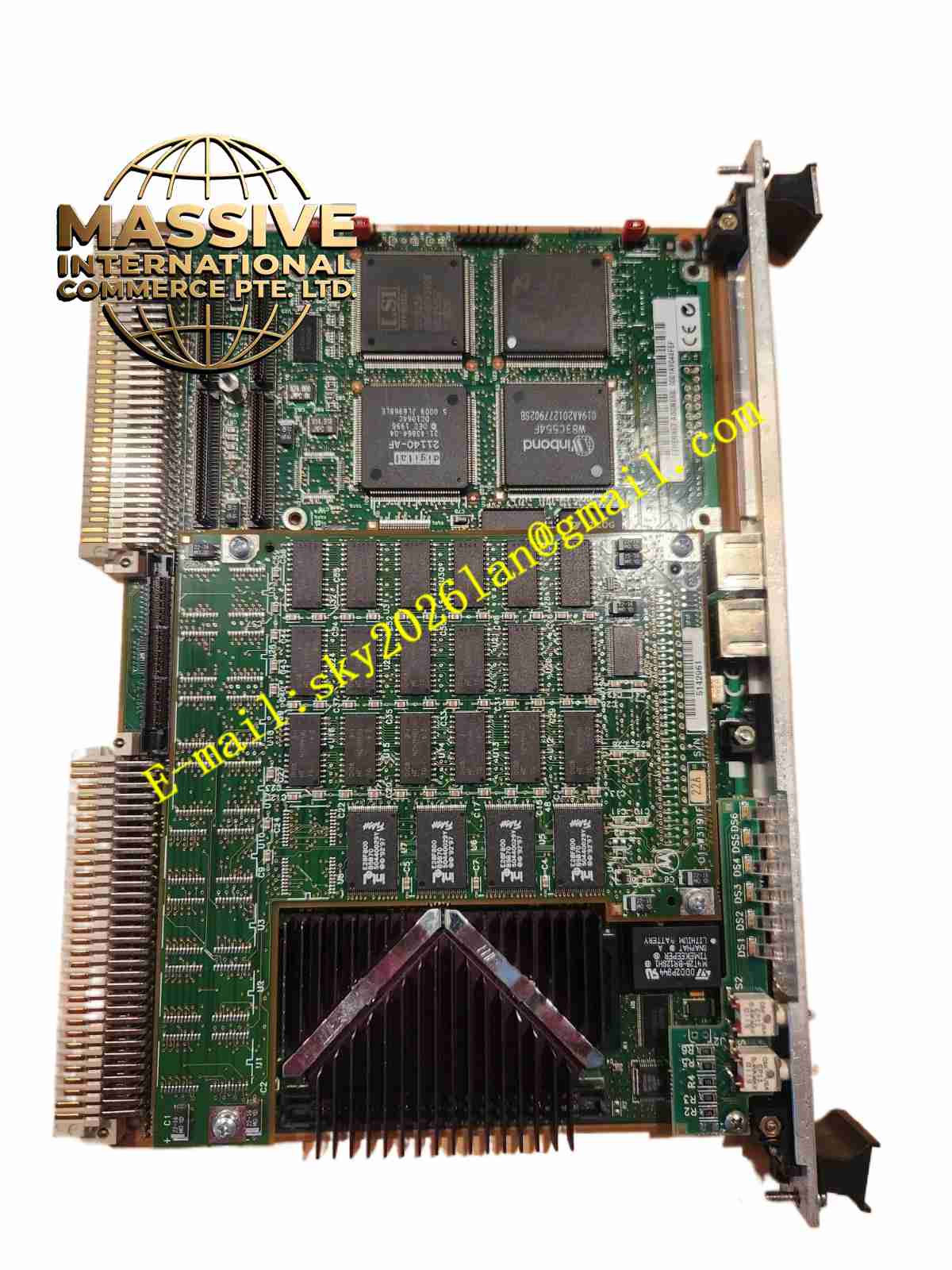
Description
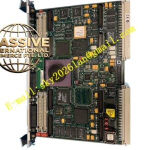
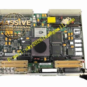
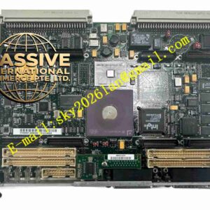
Motorola MVME2603-1121A
Technical Specifications
- Processor: PowerPC 603 microprocessor.
- Cache: Optional 256KB L2 secondary cache memory.
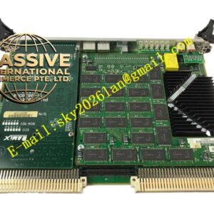
- Memory: Supports 16MB to 256MB ECC DRAM (mounted on RAM200 modules).
- Flash Memory: On-board dual 32-pin PLCC sockets (1MB 16-bit Flash), with optional 4MB or 8MB 64-bit Flash on RAM200 modules.
- Non-Volatile Storage: 8KB NVRAM with Real-Time Clock (RTC) and battery backup.
Functional Features
- PCI Bus Support: Features a PCI local bus supporting IEEE P1386.1 PMC mezzanine cards for FDDI, ATM, and other advanced I/O expansions.
- VME System Control: Supports VMEbus system controller functions and VME-to-local-bus interface (A24/A32, D8/D16/D32/block transfer).
- Ethernet Interface: Integrated DECchip 21140 PCI Fast Ethernet controller supporting AUI and 10Base-T/100Base-TX.
- SCSI Interface: Utilizes the Symbios 53C825A SCSI I/O controller for high-capacity storage devices.
Application Scenarios
Widely deployed in telecommunications equipment, industrial automation control, data acquisition systems, and real-time computing platforms in the aerospace sector.
Performance Parameters
- Power Requirements: +5V DC (±5%), typical current 5A, maximum 7A (MPC603 processor).
- Operating Temperature: 0°C to 55°C with forced-air cooling.
- Storage Temperature: -40°C to +85°C.
- Relative Humidity: 5% to 90% (non-condensing).
Material Composition
Manufactured with high-reliability industrial-grade electronic components and a multi-layer PCB design, offering excellent anti-interference capabilities and signal integrity.
Structural Characteristics
Standard Double-high VME board dimensions. Base board only height is 9.2 inches (233 mm) and depth is 6.3 inches (160 mm). With front panel and connectors, height is 10.3 inches (262 mm) and depth is 7.4 inches (188 mm), with a front panel width of 0.8 inches (20 mm).
Operating Principle
The PowerPC 603 processor manages on-board peripherals and PMC expansion cards via the PCI local bus, while exchanging high-speed data with the chassis backplane through the VME interface to execute complex real-time logic operations and control tasks.
Installation Requirements
An ESD (Electrostatic Discharge) wrist strap must be worn and grounded. The system must be powered off before inserting or removing the module. Ensure the module is fully seated on the backplane connectors without bending any pins.
Usage Precautions
Never insert or remove the module while the system is powered on, as this will damage internal components. Ensure the chassis provides adequate forced-air cooling (typically requiring 10 CFM airflow).