Description
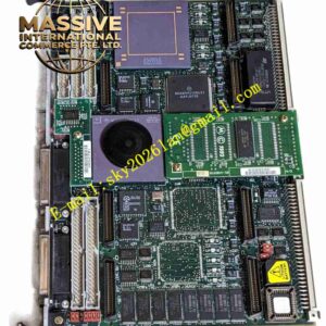
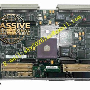
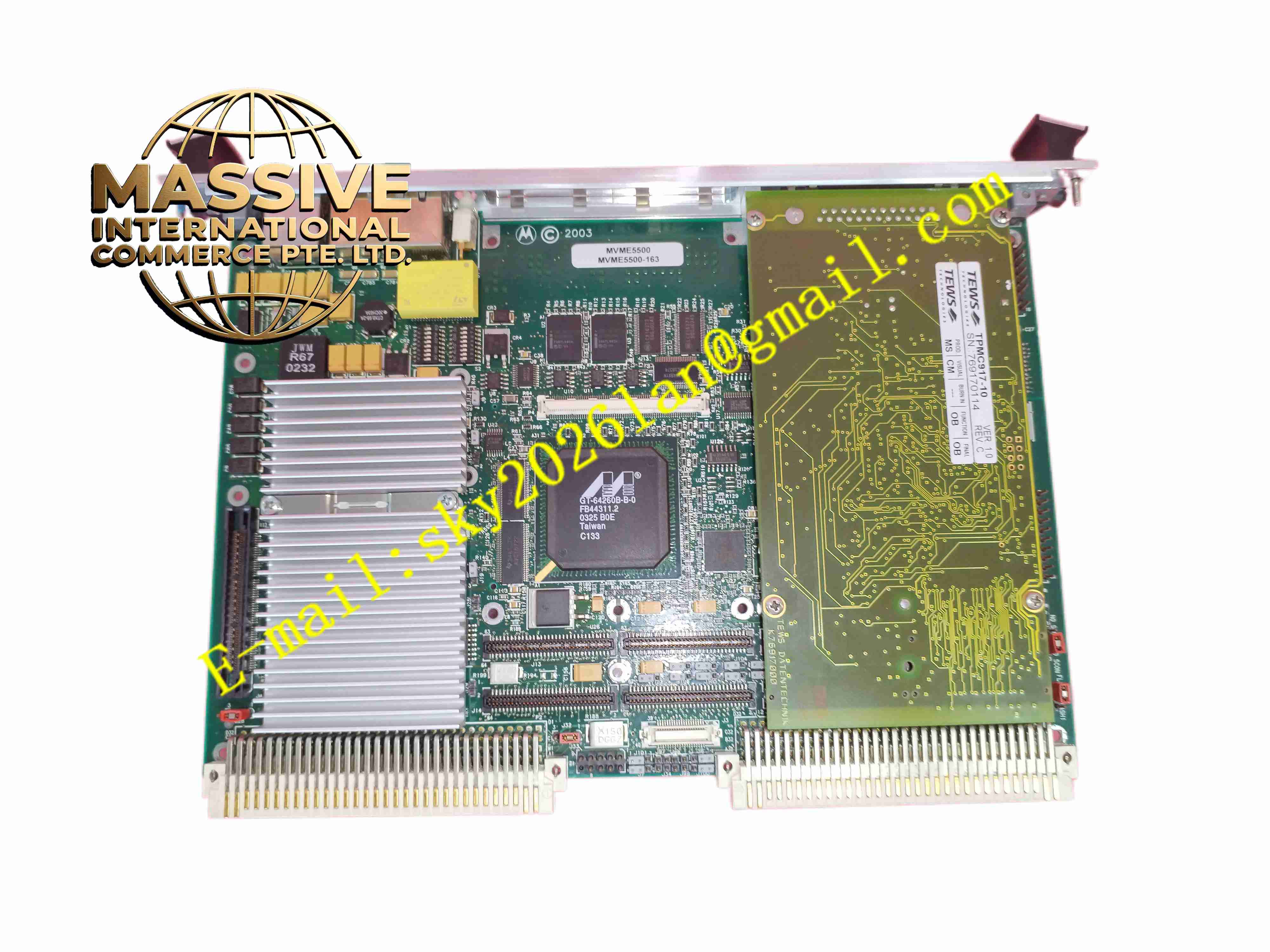
Motorola MVME550-163
Technical Specifications: Bus standard: VME64 single slot form factor Processor: PowerPC series embedded processor On-board memory: Soldered high-speed ECC SDRAM Non-volatile storage: On-board boot flash memory Communication interfaces: Ethernet port, serial debug port, VME bus interface Expansion: PMC mezzanine expansion slot Operating temperature range: 0℃ ~ +60℃ Storage temperature range: -40℃ ~ +85℃ Protection grade: IP20 when installed inside VME chassis Mounting method: VME chassis slot plug-in installation
Functional Features: High-speed embedded computing for real-time control and data processing tasks. VME bus master and slave function for data exchange with other VME modules in chassis. PMC expansion slot to add custom I/O, network or communication mezzanine cards. ECC memory function to detect and correct single bit memory error automatically. On-board flash memory stores boot firmware and embedded operating system image. Serial debug port for firmware configuration, system diagnosis and program download. Comprehensive hardware fault reporting for memory, bus and peripheral abnormality. Support CHRP standard firmware boot flow for embedded operating system startup.
Application Scenarios: Semiconductor wafer manufacturing equipment, railway vehicle control system, aerospace simulation test platform, radar signal preprocessing, large industrial testing equipment, legacy VME automation control system.
Performance Parameters: High bandwidth memory access for high-speed real-time data processing. VME64 bus high-speed data transmission between multiple VME boards. ECC error correction improves system long running reliability. Continuous operation: 24-hour uninterrupted operation in industrial chassis with cooling. Firmware supports automatic system self-test during power on startup.
Material Composition: PCB substrate: High-grade FR4 multi-layer glass fiber epoxy printed circuit board. Core components: PowerPC processor chip, ECC SDRAM memory chips, flash memory, VME bridge controller. Front panel: Aluminum alloy front panel with status LED indicators and external connectors. VME edge connector: Gold plated copper alloy edge contact pins. Metal components: Aluminum heat sink for processor thermal dissipation.
Structural Features: Standard 6U VME single slot rectangular board structure. Aluminum front panel equipped with external Ethernet port, serial debug port and LED indicators. Processor fitted with aluminum passive heat sink for heat dissipation. Internal circuit layout separated into core computing area, memory area, VME bus interface area and PMC expansion connector. VME gold edge connector for power supply and bus signal connection with VME backplane. PMC mezzanine connector for vertical mounting of auxiliary expansion card.
Working Principle: After VME chassis power on, the board runs power-on self-test program stored in on-board flash memory. The PowerPC processor loads embedded operating system and user application. The VME bridge chip manages data transmission between local PCI bus and VME backplane bus. It can work as VME master to initiate bus read and write operations, or act as VME slave responding to commands from other VME master boards. ECC memory circuit monitors memory data and automatically repairs single bit memory error. The external serial and Ethernet ports provide debugging and network data transmission channels.
Installation Requirements: Power off VME chassis before inserting or removing single board computer. Insert board into designated 6U VME slot and fasten front panel mounting screws. Connect external serial and Ethernet cables to front panel connectors. Complete firmware parameter configuration before system startup. Ensure VME chassis protective grounding is connected reliably. Chassis cooling fan must provide sufficient airflow over processor heat sink. Match PMC card clock specification when installing PMC expansion modules.
Usage Notes: Never hot plug the board when VME chassis is powered on. Backup firmware and application program before board replacement or firmware upgrade. Do not scratch gold-plated VME edge connector during handling. Wear anti-static wristband when touching bare circuit board. Regularly inspect fan working state and heat sink dust accumulation. Prevent conductive dust accumulation on board surface. Shut down chassis power before inserting or removing PMC mezzanine cards.