Description
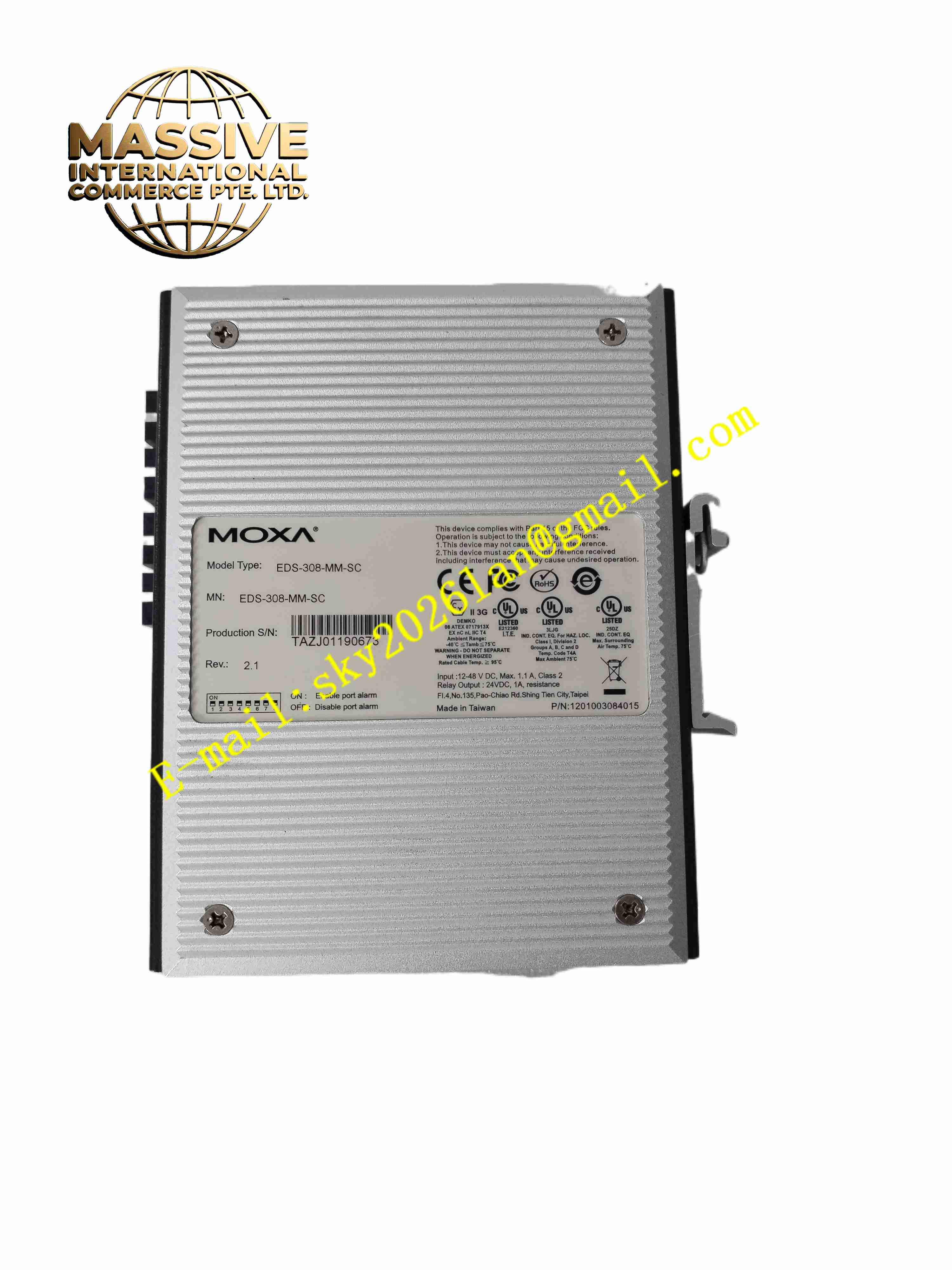
MOXA EDS-308-MM-SC
Technical Specifications
Brand: MOXA
Product Series: EDS-300 Series
Product Model: EDS-308-MM-SC
Product Type: Unmanaged Industrial Ethernet Switch
Copper Ports: 6 × 10/100BaseT(X) RJ45, auto MDI/MDI-X, auto-negotiation, full/half duplex
Fiber Ports: 2 × 100BaseFX multi-mode SC connector
Standards: IEEE 802.3, IEEE 802.3u, IEEE 802.3x
Switching Method: Store-and-forward
Flow Control: IEEE 802.3x full duplex, backpressure flow control
MAC Address Table: 1K entries
Packet Buffer: 512 Kbit
Input Voltage: 24 VDC (12–48 VDC), dual redundant inputs
Input Current: 0.26 A @ 24 VDC (MM variant)
Overcurrent Protection: 1.6 A
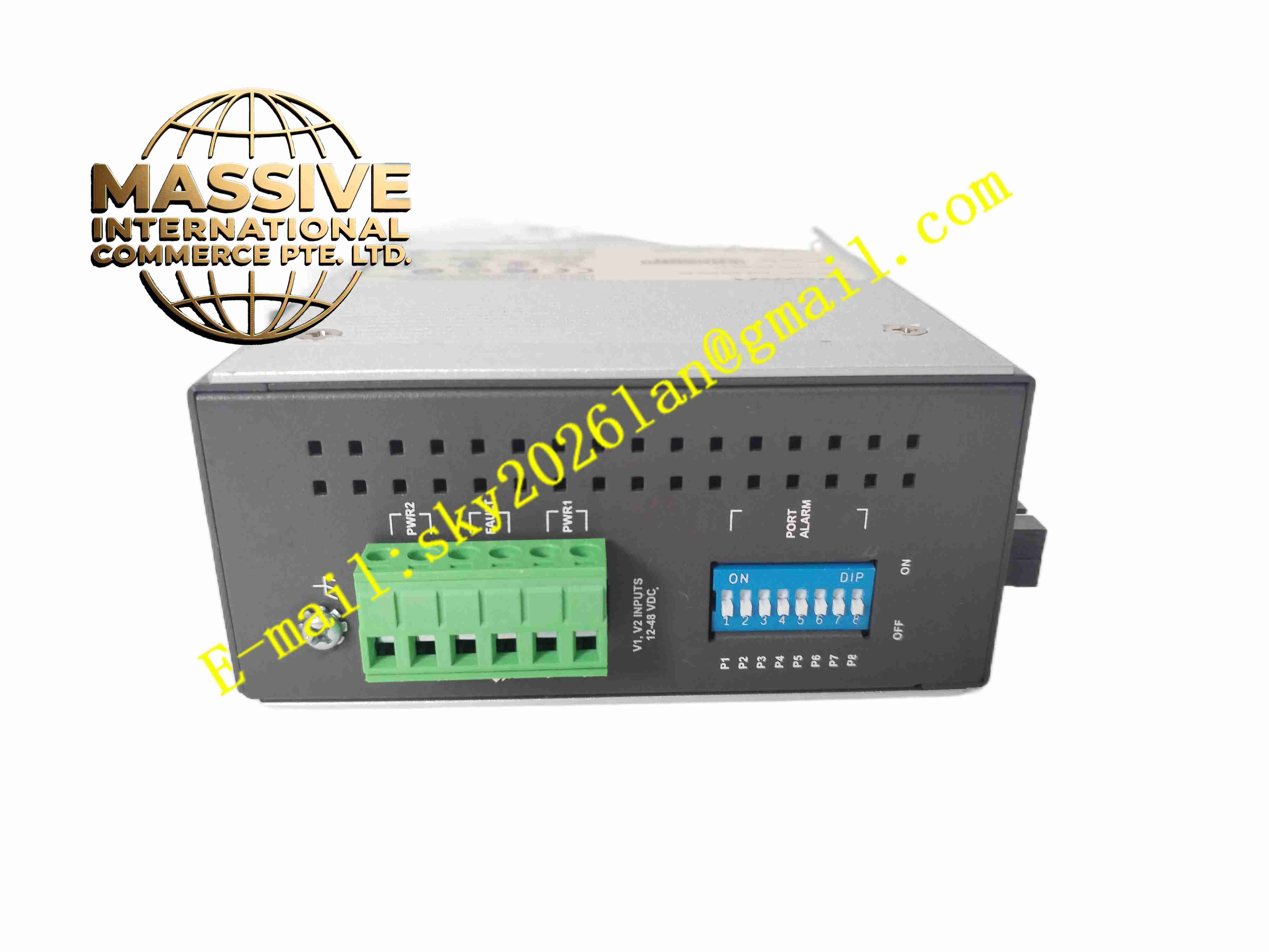
Power Connector: 1 × removable 6-pin terminal block
Reverse Polarity Protection: Yes
Alarm Output: 1 × relay output, 1 A @ 24 VDC
Protection Rating: IP30
Dimensions: 53.6 × 135 × 105 mm (W × H × D)
Weight: Approximately 630 g
Operating Temperature: 0°C to 60°C (standard model); -40°C to 75°C (wide-temperature variant)
Storage Temperature: -40°C to 85°C
Relative Humidity: 5% to 95% (non-condensing)
Certifications: FCC, UL, CE
Functional Features
Plug-and-Play Operation: No configuration required; connects and operates immediately upon power-up
Dual Redundant Power Inputs: Two independent 24 VDC power inputs ensure continuous operation if one supply fails
Smart Alarm Function: Built-in relay output alerts the control system to power failure or port link interruption
Broadcast Storm Protection: DIP switch enables or disables broadcast storm protection to prevent network flooding
VLAN Pass-Through: Transparently forwards VLAN-tagged packets without modification
Auto MDI/MDI-X: Automatically detects and adjusts cable type (straight-through or crossover) for copper connections
Auto-Negotiation: Automatically selects optimal speed (10 or 100 Mbps) and duplex mode for each copper port
Fiber Connectivity: Two multi-mode SC fiber ports support distances up to approximately 2–5 km depending on fiber type
Rugged Design: Metal enclosure with IP30 rating resists dust, vibration, and mechanical shock
High MTBF: Designed for continuous industrial operation with high mean time between failures
Application Scenarios
Factory Automation: Connecting PLCs, HMIs, and sensors on the factory floor
Process Control: Extending Ethernet networks in chemical, pharmaceutical, and food processing plants
Building Automation: Connecting HVAC controllers, access control systems, and surveillance cameras
Transportation Systems: Network infrastructure for traffic control and tunnel monitoring
Energy Infrastructure: SCADA network connectivity in substations and pipeline monitoring stations
Material Handling: Conveyor control networks in warehouses and distribution centers
Performance Parameters
Switching Capacity: 1.6 Gbps non-blocking switching fabric
Forwarding Rate: Approximately 1.19 Mpps at 100 Mbps
Latency: Less than 10 microseconds for store-and-forward switching
Packet Buffer: 512 Kbit shared buffer for burst traffic handling
MAC Address Learning: Up to 1,000 MAC addresses with automatic aging
Fiber Link Budget: Approximately 12 dB for multi-mode fiber at 1300 nm wavelength
Fiber Wavelength: 1300 nm transmit and receive
Fiber Cable Compatibility: 50/125 µm (800 MHz·km) and 62.5/125 µm (500 MHz·km) multi-mode fiber
Material Composition
Industrial-grade metal enclosure with aluminum or steel construction, IP30-rated protective housing, printed circuit board with industrial-grade electronic components, store-and-forward switching ASIC, Ethernet PHY transceivers for copper ports, fiber optic transceivers for SC ports, power supply circuitry with reverse polarity protection, relay output circuitry for alarm signaling, LED indicator components, removable terminal block connector
Structural Features
Compact rectangular metal housing with IP30 protection, DIN-rail mounting clips on the rear panel, 6 RJ45 ports on the front panel for copper connections, 2 SC fiber ports on the front panel for fiber connections, LED indicators for PWR1, PWR2, FAULT, 10/100M (copper ports), and 100M (fiber ports), DIP switches for broadcast storm protection and alarm mask configuration, removable 6-pin terminal block for dual power input and relay output, ventilation slots for passive cooling, clearly labeled port numbers and LED functions
Working Principle
The EDS-308-MM-SC receives Ethernet frames on any of its 8 ports and forwards them to the appropriate destination port based on the destination MAC address. For copper ports, the switch uses auto-negotiation to determine the optimal speed and duplex mode, and auto MDI/MDI-X to accommodate any cable type. For fiber ports, the switch converts optical signals to electrical signals for internal processing. The store-and-forward switching method ensures that each frame is fully received and checked for errors before being forwarded, preventing the propagation of corrupted frames. The dual redundant power inputs allow the switch to continue operating if one power supply fails, and the relay output provides a dry contact signal to external alarm systems when power loss or port link failure is detected.
Installation Requirements
Mount the switch on a standard DIN rail in a control cabinet or enclosure
Ensure adequate ventilation around the switch for passive cooling
Connect the 24 VDC power supply to the 6-pin terminal block (PWR1 and/or PWR2)
Connect copper devices using standard RJ45 Ethernet cables (Cat5e or higher recommended)
Connect fiber devices using multi-mode SC fiber optic cables
Verify that the fiber wavelength and cable type match the switch specifications
Configure the DIP switches as needed for broadcast storm protection and alarm masking
Verify LED indicators show normal power and link status after installation
Ground the control cabinet and ensure proper electrical safety practices
Usage Precautions
Do not exceed the rated input voltage range of 12–48 VDC
Use both power inputs for redundancy when high availability is required
Ensure fiber connectors are clean and properly seated to avoid signal loss
Do not block ventilation slots on the housing
Keep the operating temperature within the specified range of 0°C to 60°C for the standard model
Monitor the FAULT LED and relay output for power or link failure alerts
Handle fiber optic cables with care to avoid bending beyond the minimum bend radius
Refer to the official MOXA EDS-300 series user manual for detailed specifications and troubleshooting