Description
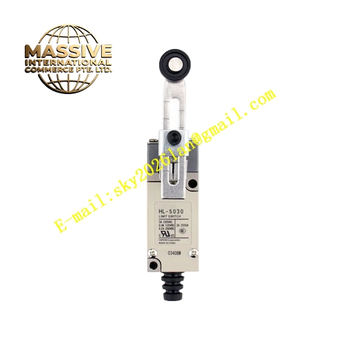
OMRON HL‑5000
Technical Specifications: Contact configuration SPDT; rated contact capacity AC250V 5A, DC30V 0.4A; mechanical durability 10 million operations minimum; electrical durability 500 000 operations under rated resistive load; operating temperature ‑10‑80°C; storage temperature ‑25‑85°C; protection rating IP64; screw terminal wiring; metal internal mechanical structure; compact housing dimension; weight approx 110g.
Functional Features: High‑strength mechanical structure resists mechanical impact and vibration; SPDT single‑pole double‑throw contact provides both normally‑open and normally‑closed signal outputs; metal actuator mechanism ensures stable stroke triggering; IP64 protection prevents dust and splash ingress; compact outline supports installation in narrow mechanical spaces; screw terminals guarantee reliable wiring connection.
Application Scenarios: Machine‑tool travel limit protection; automated machinery stroke position detection; conveyor mechanical limit position monitoring; packaging equipment mechanical position feedback; industrial machinery safety stroke interlock circuits.
Performance Parameters: Conforms to IEC60947‑5‑1 low‑voltage switchgear standard; strong vibration‑resistant performance for mechanical equipment environment; stable contact switching performance under rated load conditions.
Material Composition: Housing made of high‑strength flame‑retardant engineering plastic; internal moving mechanism zinc‑alloy metal parts; silver‑alloy contact points; brass nickel‑plated screw terminals; hardened metal actuator lever component.
Structural Features: Compact rectangular housing; replaceable mechanical actuator head; internal spring‑driven mechanical contact assembly; front‑face screw‑type wiring terminals; mounting holes on housing for fixed installation onto mechanical frames.
Working Principle: Mechanical moving parts of equipment push the actuator head of HL‑5000. Internal spring‑loaded mechanical linkage drives silver‑alloy contacts to switch between NO and NC circuits. After external mechanical force disappears, built‑in return spring resets actuator and contact state back to original condition, completing mechanical‑to‑electrical signal conversion.
Installation Requirements: Secure switch body firmly onto mechanical frame with mounting screws; adjust actuator contact position to ensure sufficient over‑travel after triggering; keep wiring terminals away from mechanical moving parts; cable layout avoids pulling stress on switch terminals.
Usage Notes: Do not exceed rated contact voltage and current parameters; avoid continuous heavy mechanical impact on actuator head; inspect contact abrasion status periodically under high‑frequency operation; do not use in environments with strong corrosive gas; keep away from long‑term liquid immersion.