Description
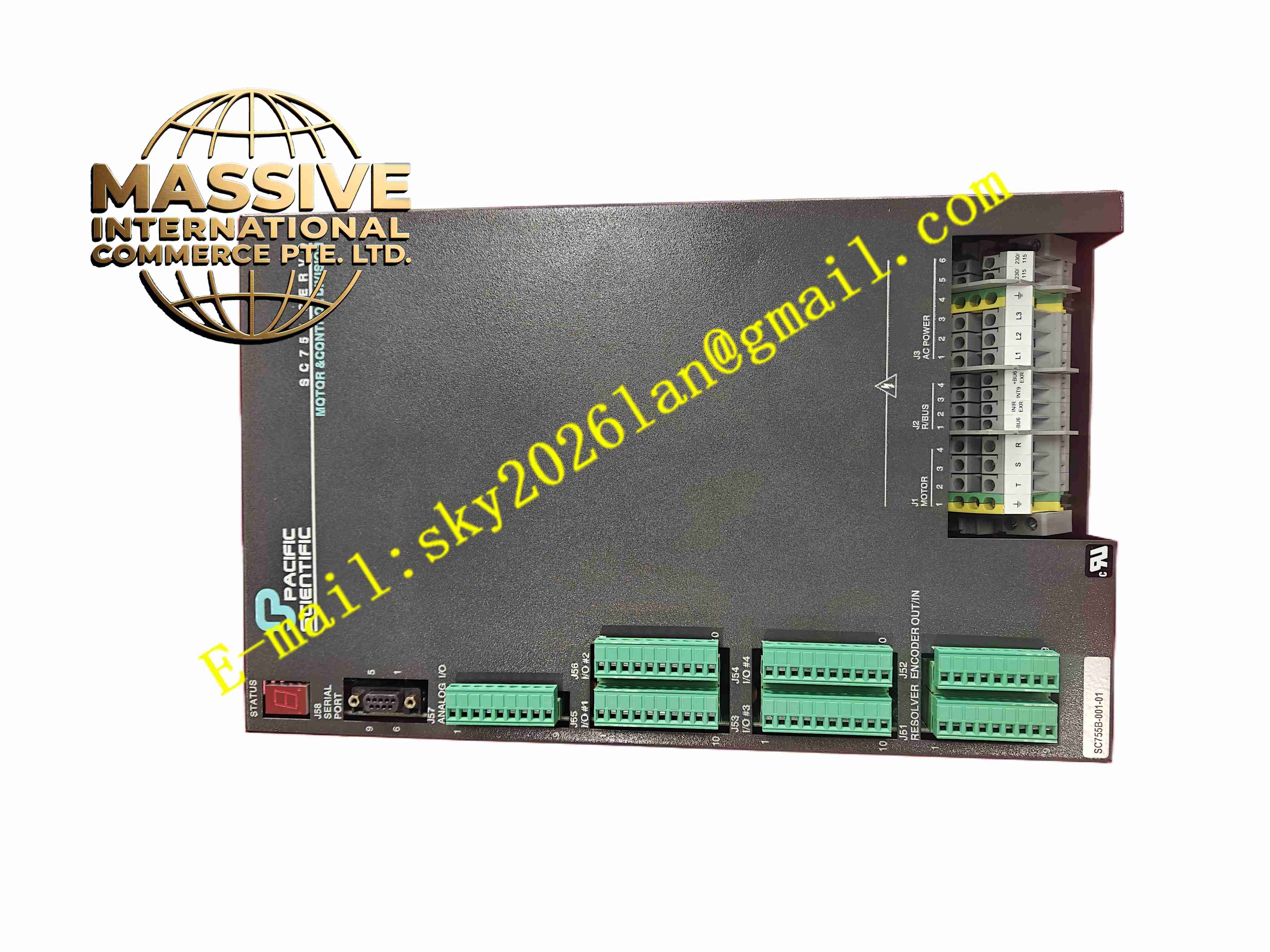
PACIFIC SCIENTIFIC SC755B-001-01
Technical Specifications: Input power: 230 VAC three-phase, 50/60 Hz Output current: 7.5 A continuous, 15 A peak Motor feedback: resolver or encoder compatible Command signal: ±10 VDC analog velocity or torque command Control loops: inner current loop, outer velocity loop Operating temperature: 0 ℃ to 40 ℃ Storage temperature: -20 ℃ to 65 ℃ Relative humidity: 5% to 95% non-condensing Mounting: panel mount
Functional Features: Three-loop closed-loop control: current, velocity and position. Adjustable loop gain parameters for system tuning. Dynamic braking resistor connection. Over-current, over-voltage and over-temperature protection. Status LED indicators for power, fault and run condition. Manual offset adjustment trim pots. Encoder feedback signal division and multiplication.
Application Scenarios: CNC machine tool servo axis drive, packaging machine motion control, printing press register control, material handling conveyor positioning, robotic arm joint drive.
Performance Parameters: Current loop bandwidth: 1 kHz Velocity loop bandwidth: 200 Hz Speed regulation accuracy: ±0.01% Power stage efficiency: greater than 95%
Material Composition: Chassis: aluminum extruded frame with heat sink. PCB: FR-4 glass fiber epoxy board. Power semiconductors: IGBT modules. Connectors: nickel-plated steel and gold-plated signal contacts.
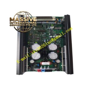
Structural Features: Panel mount rectangular chassis. Integrated aluminum heat sink on rear surface. Top cover with status LED array. Side cable glands for power and signal wiring. Internal power stage and control circuit partitioned by metal shield.
Working Principle: The drive receives analog velocity command signal. It compares command value with actual motor velocity measured by encoder feedback. The velocity loop generates current command. Inner current loop regulates motor winding current through PWM power stage. Encoder feedback provides position and velocity information. Protection circuit monitors output current and DC bus voltage continuously.
Installation Requirements: Mount vertically on flat panel surface. Keep 50 mm clearance above and below for heat dissipation. Route motor power cables away from encoder signal cables. Ground chassis protective earth securely. Tighten power terminals to specified torque.
Precautions for Use: Wait 5 minutes after power-off before servicing internal circuits. Do not exceed continuous or peak current ratings. Keep heat sink surface clean. Verify motor encoder phase sequence before enabling drive. Do not operate drive without motor connected.