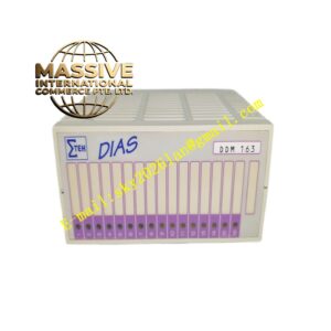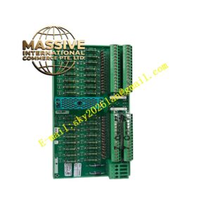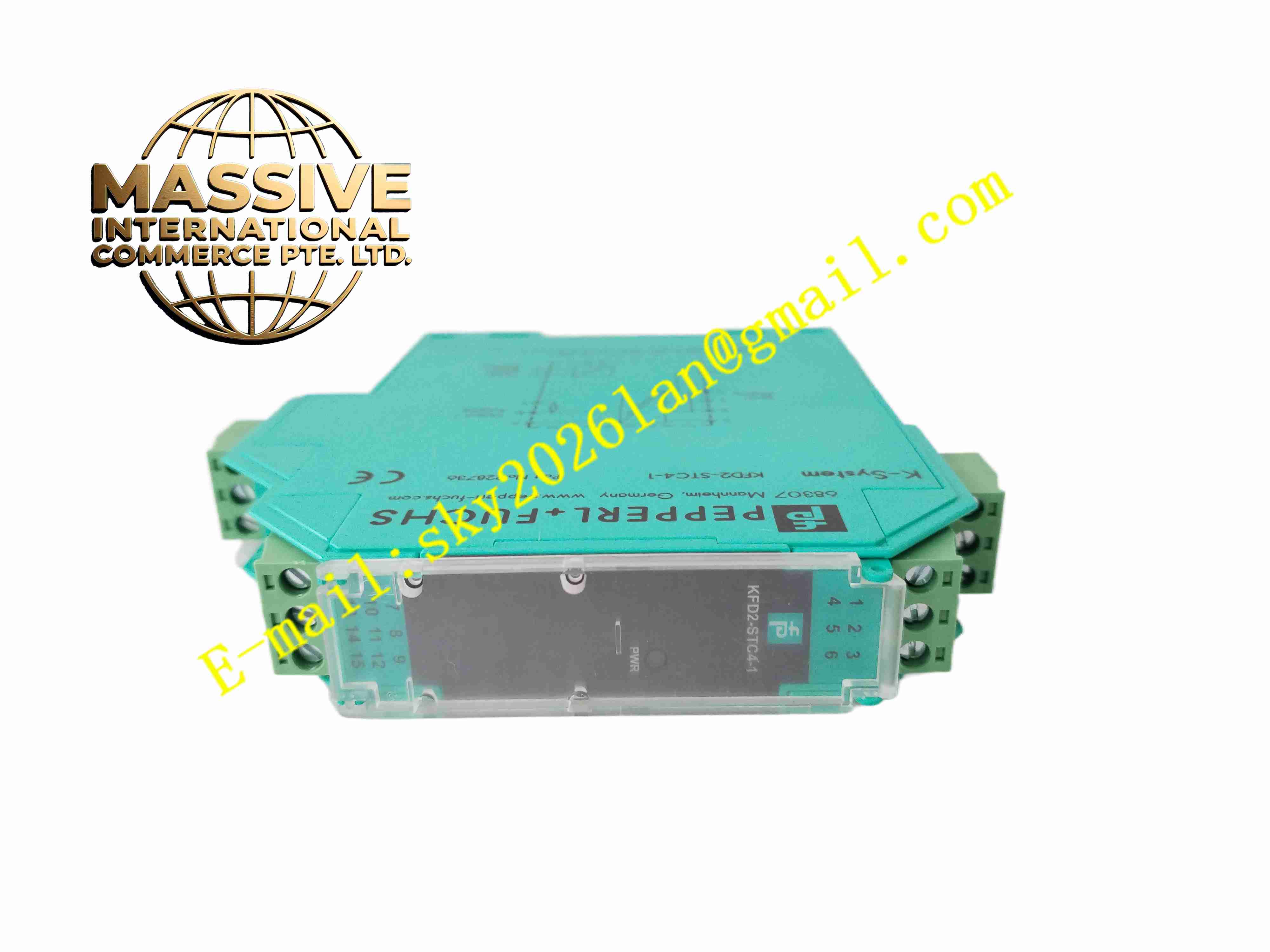
Description
Pepperl+Fuchs KFDO-TR-EX1
Technical Specifications
- Product type: Isolated barrier temperature input isolator
- Hazardous-area input: Pt100 RTD, J/K/E/N/T/R/S thermocouple
- Safe-area output: 4 to 20 mA two-wire
- Supply: DC20 to 35 V
- Loop power: Two-wire loop powered
- Isolation: 2500 VAC three-way (input, output, supply)
- Explosion protection: Ex ia IIC intrinsically safe
- Accuracy: ±0.1 % FS
- Temperature: -20 °C to +60 °C
- Storage: -40 °C to +85 °C
- Humidity: 5 % to 95 %, non-condensing
- Protection: IP20
- Installation: DIN rail
- Certifications: ATEX, IECEx, CSA
Functional Features
- Receives Pt100 RTD and thermocouple temperature signals
- Converts to 4 to 20 mA standard signal to safe-area PLC
- Three-way 2500 VAC isolation
- Ex ia IIC intrinsically safe design
- Supplies hazardous-area two-wire temperature transmitters
- Range configurable by hardware jumper or software
- Automatic thermocouple cold junction compensation
- Front panel LEDs for power and operating status
- Input loop wire-break detection with alarm current output
- Compact DIN rail mounting saving cabinet space
Application Scenarios
- Hazardous-area temperature signal isolation in petrochemical plants
- Chemical reactor temperature acquisition
- Oil/gas platform and refinery temperature intrinsic-safe isolation
- Pharmaceutical explosive-area temperature measurement
- Offshore platform hazardous-area temperature monitoring
Materials and Construction
- Housing: Flame-retardant engineering plastic
- PCB: FR4 board with conformal coating
- Core: Temperature signal conditioning chip, isolation transformer
- Passive components: Metal film resistors, ceramic capacitors, TVS diodes
- Terminals: Screw-fastened tin-plated terminals
- Mounting clip: 35 mm DIN rail clip
Structural Features
- Narrow DIN rail plastic housing, about 17.5 mm width
- Top and bottom terminals separated into hazardous and safe sides
- Terminal blocks clearly marked Ex side and safe side
- Internal partitions between hazardous intrinsic-safe, isolation, and safe areas
- Isolation transformer centered on board for three-way isolation
- Fanless natural convection
Working Principle Hazardous-area Pt100 or thermocouple signals enter input terminals; conditioning circuitry amplifies and cold-junction-compensates, then transfers across an isolation transformer to the safe-area output circuit. The output circuit reconstructs a 4 to 20 mA current sent to the PLC. The isolation transformer provides 2500 VAC three-way isolation; intrinsic-safe current/energy limiting restricts hazardous-side energy within Ex ia limits. In loop-powered mode, safe-side 24 V powers the field two-wire transmitter through isolation. LEDs indicate operating status.
Installation Requirements
- Snap-mount on 35 mm DIN rail
- Strictly connect hazardous and safe side terminals per markings
- Use intrinsic-safe cable on hazardous side
- Connect safe-side output to AI card
- Supply DC24 V per drawing
- Ground intrinsic-safe circuits per explosion-protection rules
- Cabinet temperature -20 °C to +60 °C
Precautions
- Never reverse hazardous and safe side terminals
- Intrinsic-safe cables must not share trays with non-intrinsic-safe cables
- Field intrinsic-safe device parameters must match the barrier
- Explosion-protection parameter changes by qualified personnel only
- Store spares in dry moisture-proof packaging
- Disconnect power before service