Description
Phoenix Contact PSR-SPP-24UCURM45X12X2B Safety Relay Module
Technical Specifications Model: PSR-SPP-24UCURM45X12X2B Supply Voltage: 24V AC / DC Safety Input: Dual-channel safety signal input Safety Output: Force-guided safety contact Safety Category: PLd, SIL2 Response Time: Short reaction time upon safety signal trigger Operating Temperature: -25℃ ~ +60℃ Storage Temperature: -40℃ ~ +85℃ Relative Humidity: 5% ~ 95% non-condensing Mounting Method: DIN rail mounting inside control cabinet Protection Grade: IP20 for module body
Functional Features Dual-channel redundant input circuit monitors safety signal to detect short circuit and wire break fault of safety wiring. Force-guided safety contact ensures reliable disconnection of output circuit under fault state. Automatic startup and manual startup selectable mode for different machine safety requirements. Built-in internal self-monitoring circuit checks relay contact state and internal circuit continuously. LED indicators display power status, input signal state and safety output state. SIL2 and PLd safety certification provides high safety integrity level for machine protection. Compact housing design saves cabinet installation space. Wide voltage range of 24V AC/DC power supply adapts to different industrial control power supply systems.
Application Scenarios Machine tool emergency stop safety circuit, packaging machinery safety door interlock, conveyor safety protection system, robot peripheral safety light curtain control, textile machinery safety protection circuit.
Performance Parameters Dual-channel fault detection circuit reliably identifies cross short circuit and cable break of safety input wiring. Force-guided contacts guarantee mechanical forced separation of contacts under internal relay failure. Module maintains stable safety judgment function under continuous mechanical vibration in workshop. Internal self-test runs in each operation cycle to detect internal component degradation. Safety output contact acts rapidly when safety input signal is interrupted. LED status indicators provide clear visual diagnosis information for maintenance staff.
Material Composition Module housing: Flame-retardant PA plastic housing. Main PCB: FR4 printed circuit board with protective coating. Core electronic components: Safety relay with force-guided contact, monitoring logic chip, transient suppression diode, input filter circuit. Terminal parts: Screw type wiring terminals made of copper alloy. Fasteners: Metal DIN rail clamping clip. Indicator components: Light emitting diodes for state indication.
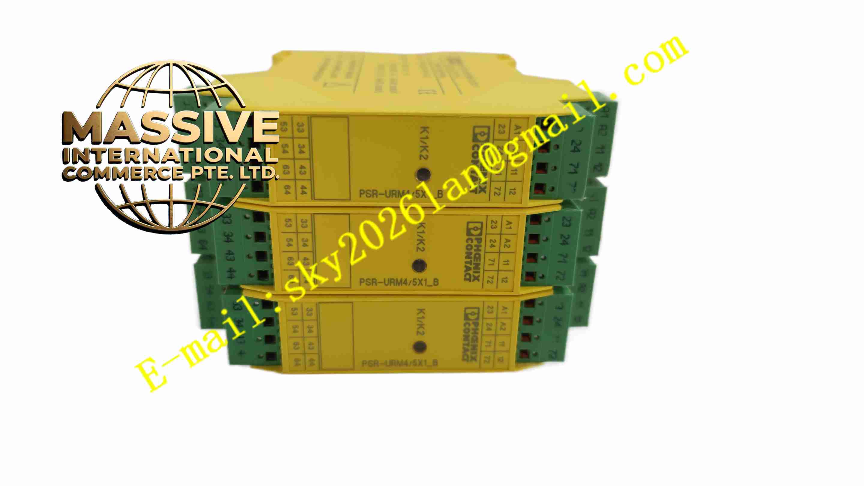
Structural Features Compact rectangular plastic housing designed for DIN rail installation. Screw terminals arranged on front side for safety input, power supply and safety output wiring. LED status indicators on front panel for visual inspection. Metal spring clip fixed on module back for locking on DIN rail. Internal layout separates low voltage logic circuit and power contact circuit. Module housing has isolation barrier between adjacent wiring terminals to prevent short circuit.
Working Principle 24V AC or DC power supplies internal monitoring circuit and safety relay coil. Dual safety input terminals receive signals from safety door switch or emergency stop button. The internal logic circuit continuously compares signal state of two input channels. If the two channels keep normal consistent signal, the safety relay coil remains energized, safety contacts close and output circuit keeps connected. Once safety button is pressed or safety door opens, dual input signal changes, internal circuit de-energizes safety relay coil immediately, force-guided safety contacts open to cut off power supply of dangerous actuator. The self-monitoring circuit checks relay contact state and wiring fault continuously, locks safety output state and triggers fault indication if internal fault is detected.
Installation Requirements Mount module on standard DIN rail inside control cabinet, lock the back spring clip tightly. Complete wiring according to wiring diagram, connect emergency stop or safety door switch to dual input terminals. Connect actuator control circuit to safety output contact terminals. Connect 24V AC/DC power supply to module power terminal. Set startup mode parameter according to machine safety requirement. Power on and perform safety function test after wiring completion. Keep module away from high voltage frequency converter cables to reduce electromagnetic interference.
Usage Precautions Module body is IP20 protection grade, install inside closed control cabinet only. Strictly follow safety standard for wiring of dual safety input channel, do not omit dual-channel wiring. Check wiring integrity and contact tightness periodically during regular maintenance. Do not modify internal circuit of safety relay module, any modification invalidates safety certification. Select load within rated contact capacity for safety output circuit. Test emergency stop and safety door interlock function before machine startup after wiring modification. Replace module when internal fault alarm appears.