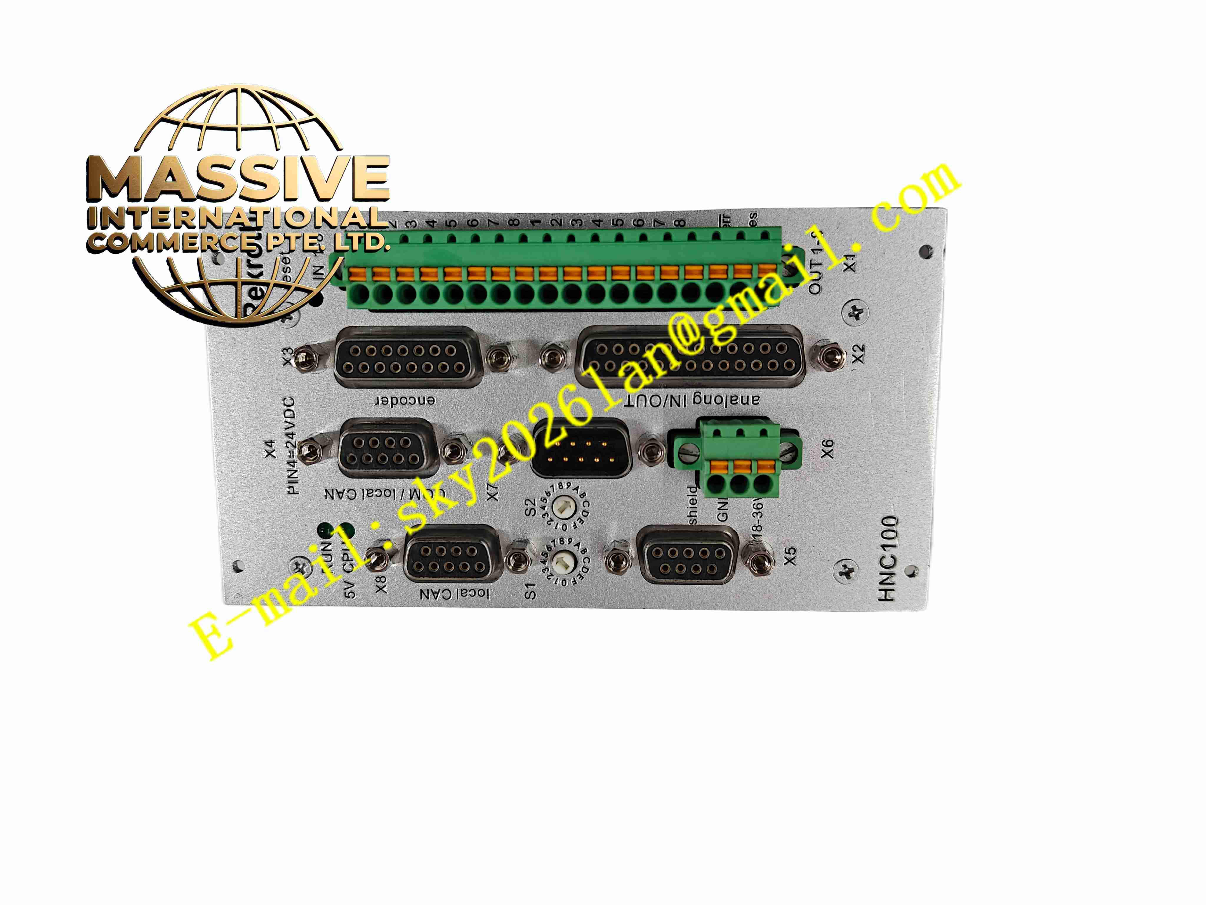
Description
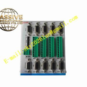
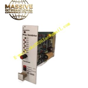
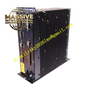
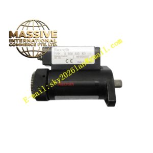
Rexroth HNC100 SYHNC100-BLA-23W-08-C-0-E23-A014
Technical Specifications
- Product Type: Digital hydraulic axis motion controller
- Power Supply: 24 V DC
- Feedback Input: Incremental encoder, analog position sensor, pressure / force analog signal
- Control Modes: Position closed-loop, force closed-loop, pressure closed-loop control
- Communication Interfaces: PROFIBUS DP, CANopen, RS232 for WIN-PED configuration software
- Digital Inputs: 11 optically isolated discrete inputs
- Digital Outputs: 11 discrete outputs, max 20 mA per channel
- Valve Output: Analog ±10V output for hydraulic proportional and servo valves
- Configuration Software: WIN-PED 6
- Protection Rating: IP00 for module, IP20 when installed in control cabinet
- Operating Temperature: 0 °C to +55 °C
- Mounting: Rack plug-in module for Rexroth control cabinet
- Cooling: Passive convection cooling
Functional Features
- High-speed closed-loop control for hydraulic servo axes with position, force and pressure regulation modes.
- Support multiple feedback types including incremental encoder and analog displacement transducer.
- Analog ±10V output drives hydraulic proportional valve and high-response servo valve.
- PROFIBUS DP and CANopen bus communication exchange setpoint and status data with upper PLC.
- Built-in motion profile generator executes point-to-point positioning and continuous motion sequences.
- Auto-tuning function optimizes control loop parameters for different hydraulic mechanical loads.
- Digital I/O channels handle machine limit, enable, emergency stop and axis status signals.
- Fault diagnostic function records fault codes and waveform data for hydraulic axis troubleshooting.
- Parameter memory stores axis configuration and control loop gain settings.
- Hot swap capability for replacement during machine planned maintenance shutdown.
Application Scenarios
- Heavy hydraulic press machine single axis closed-loop control
- Injection molding machine hydraulic axis precision positioning
- Metal forming and stamping equipment hydraulic servo control
- Steel mill rolling mill hydraulic cylinder position and force control
- Test bench hydraulic loading and force control system
Material Composition
- Main PCB: FR4 high reliability printed circuit board with conformal coating
- Control processor: High speed digital signal processor
- Signal acquisition components: Precision instrumentation amplifier and A/D converter chips
- Communication components: PROFIBUS and CANopen transceiver chips
- Backplane connector: Gold-plated copper edge contact pins
- Terminal blocks: Tin-plated copper alloy screw terminals
- Front panel: Flame-retardant polycarbonate plastic with LED indicators
Structural Characteristics
- Rectangular plug-in rack module with front panel handle and locking lever.
- Front panel equipped with LED indicators for module power, run and fault status.
- Rear gold-plated edge connector inserts into Rexroth control rack backplane bus.
- Independent signal conditioning circuit for feedback sensor inputs.
- Internal circuit layout separates low level analog sensor circuit and digital logic circuit.
- Conformal coating protects PCB surface against moisture and airborne contaminants.
Working Principle Upper PLC sends motion setpoint via fieldbus to HNC100 controller. The controller reads real-time feedback signal from displacement, pressure or force sensor installed on hydraulic cylinder. DSP compares setpoint value and actual feedback value, calculates control output through PID control algorithm. Analog ±10V control signal transmits to hydraulic servo or proportional valve to adjust hydraulic flow and cylinder movement. Digital I/O circuit reads machine limit and emergency stop signals, outputs axis ready and fault status to PLC. When fault condition exceeds threshold, controller cuts valve output and triggers safety interlock.
Installation Requirements
- Insert SYHNC100-BLA-23W-08-C-0-E23-A014 module into designated slot of Rexroth control rack.
- Use shielded twisted pair cable for hydraulic sensor and valve wiring.
- Separate analog sensor cables from high power motor and hydraulic power unit cables.
- Complete protective earth connection for rack and control cabinet.
- Execute hydraulic axis setup and servo loop auto-tuning after wiring completion.
- Test limit switch, home switch and emergency stop interlock circuit.
- Verify feedback sensor wiring polarity before full load operation test.
Usage Notes
- Do not exceed rated input voltage and signal range for feedback terminals.
- Keep cabinet dry and free of oil mist and conductive dust.
- Backup axis parameter settings before firmware upgrade or configuration modification.
- Disconnect power before modifying sensor or valve wiring.
- Use anti-static wristband when handling spare controller module.
- Replace module immediately when permanent control algorithm or signal acquisition fault occurs.