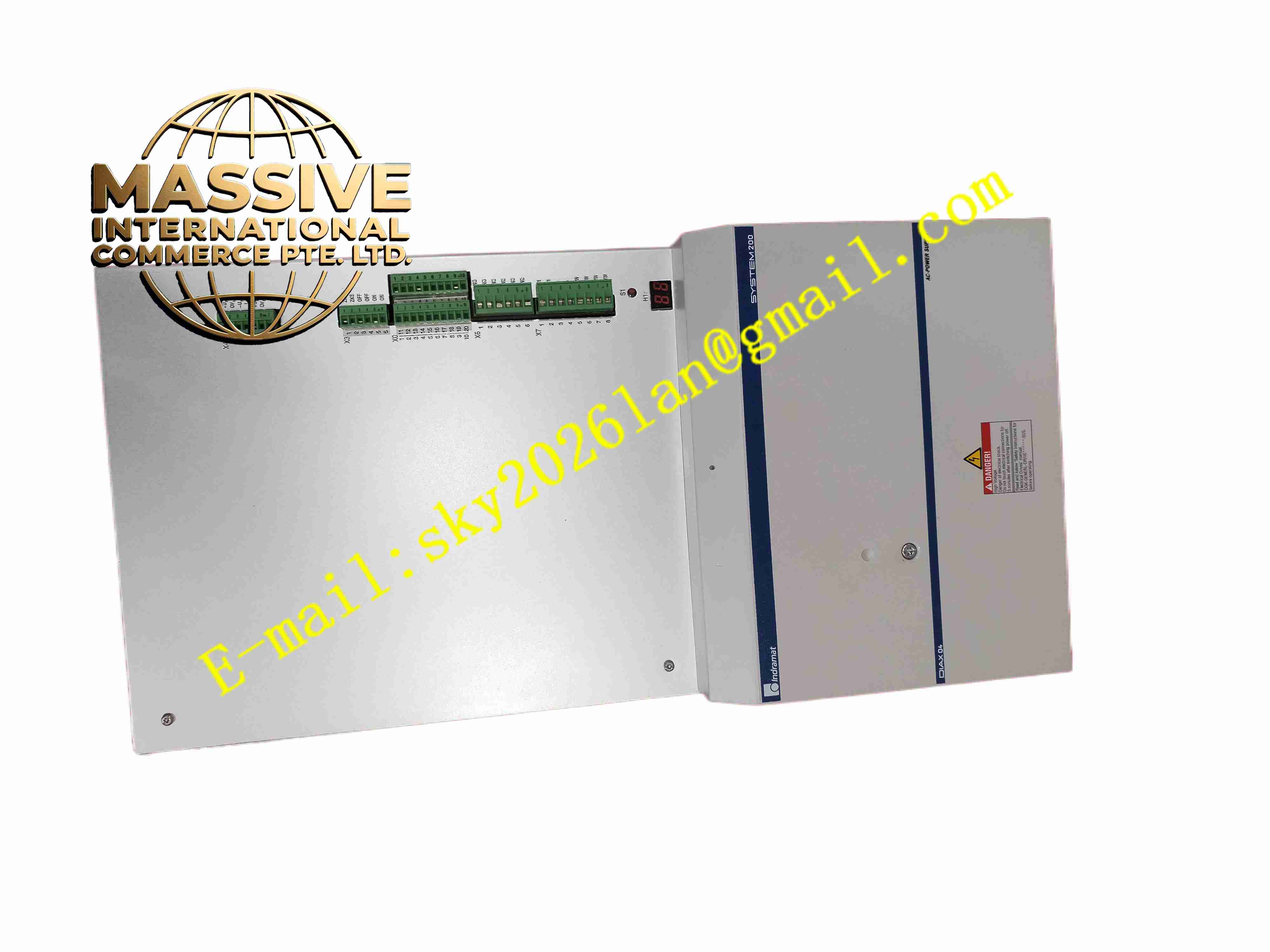
Description
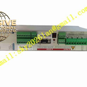
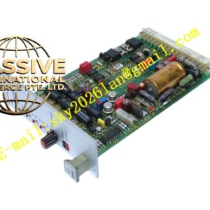
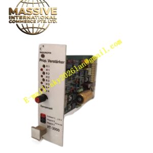
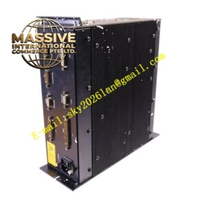
Rexroth HVE04.2-W075N
Technical Specifications
- Product Type: AC to DC common bus power supply module
- Input Power: 3 × 380 V AC to 480 V AC, 50 Hz / 60 Hz, ±10 % tolerance
- Rated Power: 75 kW, continuous DC bus power 90 kW
- DC Bus Output: 400 V DC to 480 V DC regulated bus voltage
- Peak Regenerative Power: 270 kW, continuous bleeder power 2.5 kW
- Diagnostic Interface: Front HI diagnostic display for fault code and status
- Protection Functions: Overvoltage, undervoltage, overcurrent, overtemperature, short circuit
- Protection Rating: IP10
- Operating Temperature: 4 °C to +45 °C
- Mounting: Rack plug-in module for Rexroth DIAX04 drive cabinet
- Cooling: Built-in blower forced air cooling
- Weight: 20 kg
Functional Features
- Three-phase AC to DC conversion provides common regulated DC bus for multiple servo axis modules.
- Internal brake bleeder circuit dissipates excess regenerative energy from servo motor deceleration.
- Front diagnostic display shows real-time operating status and fault alarm codes.
- Hardware protection circuit monitors bus voltage, current and module temperature continuously.
- Power ready relay output sends enable signal to servo axis modules after bus voltage stabilizes.
- Rack bus communication exchanges status and fault information with servo modules.
- Modular rack design supports multi-axis servo system expansion.
- Built-in input filter suppresses mains side electromagnetic interference.
- Pre-charge circuit limits inrush current during power on to protect internal capacitors.
- Fault latch function retains fault code after power loss for maintenance diagnosis.
Application Scenarios
- Multi-axis CNC machine tool DIAX04 servo drive rack power supply
- Large gantry automation equipment multi-axis motion control system
- Metal forming machine multi servo axis common bus power source
- Packaging heavy machinery multi-axis servo drive system
- Test bench multi-axis high dynamic motion equipment
Material Composition
- Enclosure: Galvanized steel sheet metal casing
- Main PCB: FR4 printed circuit board with conformal coating
- Power components: High power IGBT rectifier modules, DC bus electrolytic capacitors
- Control processor: Industrial digital signal processor
- Terminal blocks: High current nickel-plated copper screw terminals
- Cooling components: High flow axial blower and aluminium heat sink
- Communication connectors: Gold plated backplane edge connectors
Structural Characteristics
- Vertical plug-in rack module with metal housing and front handle for extraction.
- Front panel integrates diagnostic display, status LED and ventilation grille.
- Rear high current terminals for three-phase AC mains input and protective earth connection.
- Backplane edge connector communicates with rack bus and supplies DC bus to servo axis modules.
- Internal heat sink mounted on IGBT power devices for heat dissipation.
- Internal pre-charge circuit and bus capacitor bank arranged inside metal housing.
Working Principle Three-phase AC mains power enters HVE04.2-W075N input terminals. Pre-charge circuit activates at power on to limit inrush current and charge DC bus capacitors. IGBT rectifier converts AC power into regulated DC bus voltage, supplied to all servo axis modules on the same rack. When servo motor decelerates, regenerative energy flows back to DC bus and raises bus voltage. If bus voltage exceeds threshold, internal bleeder circuit activates and converts excess energy into heat. Monitoring circuit tracks voltage, current and temperature continuously, cuts off power input and triggers fault indication when protection threshold is exceeded.
Installation Requirements
- Insert HVE04.2-W075N module into designated slot of Rexroth DIAX04 drive rack.
- Use heavy gauge shielded power cable for three-phase mains input wiring.
- Separate high power mains cable from low voltage signal and encoder cables.
- Complete protective earth connection for module housing and rack.
- Verify phase sequence of three-phase AC input before power energization.
- Perform pre-charge test and DC bus voltage measurement after wiring completion.
- Check blower airflow and heat sink condition before full load operation test.
Usage Notes
- Do not operate module with cooling blower failure.
- Keep cabinet air inlet filter clean to prevent dust accumulation blocking airflow.
- Do not exceed rated input voltage and maximum regenerative power specification.
- Disconnect three-phase AC input power and fully discharge DC bus capacitors before opening module or modifying wiring.
- Backup system parameter settings before configuration modification.
- Use anti-static wristband when handling spare module and backplane connectors.
- Replace module immediately when permanent rectifier or bus regulation hardware fault occurs.