Description
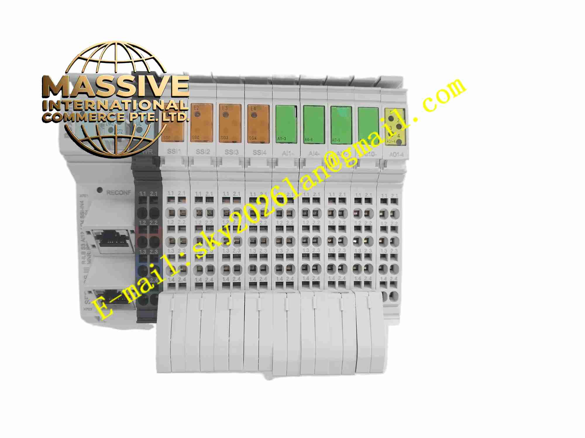
Rexroth R-ILB S3 AI12 AO4 SSI-IN4 R911171949
Technical Specifications Model: R-ILB S3 AI12 AO4 SSI-IN4 Part Number: R911171949 Brand: Bosch Rexroth Power Supply: 24V DC industrial auxiliary power Analog Input Channels: 12 analog input channels Analog Output Channels: 4 analog output channels SSI Input Channels: 4 SSI absolute encoder input channels Communication: Industrial fieldbus interface Operating Temperature: 0 ℃ ~ +55 ℃ Storage Temperature: -40 ℃ ~ +85 ℃ Relative Humidity: 5% ~ 90%, non-condensing Mounting: NS35 DIN rail mounting Protection Class: IP20 Signal Type: 4-20mA or 0-10V analog signal, SSI serial position signal
Functional Features 12 analog input channels acquire continuous measurement signals from pressure, temperature, flow and level transmitters. 4 analog output channels generate adjustable 4-20mA or 0-10V analog signals to control proportional valves and regulators. 4 independent SSI input channels receive high-resolution serial position data from absolute rotary and linear encoders. Per-channel hardware self-diagnosis detects open circuit, short circuit and signal over-range fault. Fieldbus communication transmits collected measurement and position data to PLC or motion controller and receives control commands. Front panel LED indicators show module power status, bus communication state and individual channel fault. Built-in signal filtering circuit suppresses high-frequency noise interference on analog and SSI signal lines. Non-volatile memory stores module address, channel parameter configuration and fault event logs.
Application Scenarios Machine tool axis position measurement, packaging machinery process signal acquisition, hydraulic press proportional valve control, automated assembly line sensor monitoring, material handling lifting equipment position feedback, metal processing machinery motion measurement, textile machinery analog control system.
Performance Parameters Analog input channels maintain high measurement accuracy under industrial electromagnetic interference. Analog output channels deliver stable analog signal output with low waveform distortion. SSI input channels capture high-speed serial position data from absolute encoders without data loss. Per-channel fault diagnosis circuit identifies wiring failure and triggers alarm instantly. Fieldbus communication maintains real-time and stable data transmission in factory workshop environment. Configuration parameters remain fully preserved after power interruption. Signal filtering circuit effectively eliminates high-frequency noise on field signal cables.
Material Composition Housing: Black flame-retardant engineering plastic housing and metal shielding frame. Main PCB: FR4 multi-layer industrial printed circuit board coated with conformal protective coating. Core Electronic Components: ADC sampling chips, DAC output chips, SSI serial receiving chips, fieldbus transceiver, microcontroller, EMC surge protection components, non-volatile memory chip. Terminal Parts: Gold-plated copper alloy screw terminals for power, analog signal and SSI signal wiring. Indicator Components: LED status indicators arranged on front panel. Fasteners: Stainless steel screws and DIN rail spring locking clip.
Structural Features Compact rectangular DIN rail module structure for electrical cabinet installation. Front panel is equipped with LED indicators and module part number marking. Rear side integrates screw terminals for 24V DC power supply, analog signals and SSI encoder signals. Metal shielding frame reduces electromagnetic emission and external interference. Internal circuit strictly separates analog measurement circuit, SSI high-speed serial circuit and fieldbus digital circuit. Ventilation slots are reserved on housing surface for natural convection heat dissipation.
Working Principle 24V DC industrial power supplies the internal circuit of Rexroth remote I/O module. Field transmitters connect to analog input terminals. ADC chips convert continuous analog signals into digital values for microcontroller processing. Absolute SSI encoders connect to SSI-IN4 terminals, and serial position data is decoded by dedicated SSI receiving chips. The microcontroller packages all measurement data and position information and transmits data to upper controller via industrial fieldbus. When receiving control command from upper controller, DAC chips convert digital control value into analog output signal and send signal to field proportional actuators. Onboard diagnosis circuit continuously monitors every input and output channel. When channel abnormality appears, fault LED lights up and fault information uploads to upper control system.
Installation Requirements Mount the module on NS35 DIN rail inside closed industrial electrical cabinet and lock spring clip firmly. Connect 24V DC power cable, analog sensor cables and SSI encoder cables to corresponding terminals following official wiring drawing. Use shielded twisted pair cables for analog and SSI signal wiring and apply single-point grounding for shielding layer. Complete protective earth grounding of module metal shielding frame. Set module station address, signal type and channel parameters via Rexroth configuration software. Conduct channel calibration and full function test after wiring and parameter setup. Keep high-power motor and inverter cables separated from signal cables to avoid interference.
Usage Precautions Do not apply voltage or current exceeding rated range to analog and SSI terminals. Ensure reliable protective earth connection to guarantee EMC performance and operator safety. Do not operate the module in environment with condensation, corrosive gas or conductive dust. Do not disassemble module housing without professional authorization. Back up all module configuration parameters before maintenance or module replacement. Cut off module power before modifying field sensor or encoder wiring. Check terminal screw tightness regularly during routine equipment maintenance.