Description
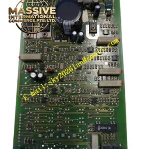
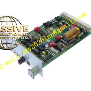
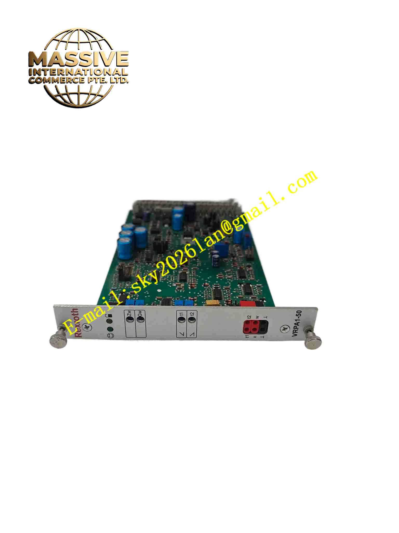
Rexroth R900952202 VT-VRPA1-50-1X
Technical Specifications Model: VT-VRPA1-50-1X Part Number: R900952202 Form Factor: Euro-card printed circuit board, 100 × 160 mm Power Supply: DC operating power supply Command Input: Analog voltage or current differential input Output: Drive current for proportional valve solenoid Feedback Signal: Valve position sensor signal input Mounting: Insert into 19 inch rack subrack Operating Temperature: 0 ℃ ~ +60 ℃ Storage Temperature: -20 ℃ ~ +85 ℃ Relative Humidity: 5% ~ 95% non-condensing Front Panel: Adjustment potentiometers and LED status indicator
Functional Features Differential analog command input, switchable between voltage signal and current signal. Closed-loop control processing of valve spool position feedback signal. Adjustable zero point, gain and ramp time via front panel potentiometers. Reverse polarity protection for module operating power supply. Enable input terminal to activate or disable valve output. LED indicator shows ready operation state. Output terminals for command value monitoring and actual feedback signal monitoring. Short-circuit protection for solenoid drive output.
Application Scenarios Hydraulic press machine proportional valve control, injection molding machine hydraulic servo control, metallurgy rolling mill hydraulic control system, test bench hydraulic actuator control, heavy machinery proportional pressure and flow control.
Performance Parameters Closed-loop control circuit reduces steady-state error of proportional valve spool position. Ramp generator limits output current changing rate to avoid hydraulic impact. Protection circuit cuts off output when solenoid short circuit occurs. Front panel potentiometer realizes continuous adjustment of zero and gain parameters. Module maintains stable drive output under long continuous operation in hydraulic cabinet. Differential input circuit suppresses common-mode interference from control signal wiring.
Material Composition PCB: FR4 industrial printed circuit board with protective coating. Core Electronic Components: Operational amplifiers, power output stage transistors, reference voltage chip, potentiometers, transient suppression diodes, protection fuses. Terminal Connector: Edge connector for subrack backplane connection. Adjustment Components: Metal multi-turn potentiometers mounted on front panel. Indicator Components: LED status indicator on front panel. Fasteners: Metal front panel fixing bracket.
Structural Features Standard Euro-card PCB dimension for 19-inch rack subrack installation. Metal front panel equipped with adjustment potentiometers, LED indicator and marking text. Gold-plated edge connector at rear of PCB inserts into subrack backplane socket. Internal circuit layout separates low-level analog command circuit and high-power solenoid drive circuit. Front panel metal bracket provides mechanical fixation and electromagnetic shielding. Signal terminals are arranged on subrack backplane connected with PCB edge connector.
Working Principle DC operating power supplies the amplifier card internal circuit. Low-level analog command signal from upper controller enters differential input terminal. The command value signal is compared with valve spool position feedback signal from valve internal position sensor. The error signal passes through amplifier circuit and ramp limiter, then drives power output stage. Power output stage generates proportional drive current to control proportional valve solenoid coil. The spool moves with electromagnetic force of solenoid, and position sensor feeds back actual spool position signal to amplifier card to form closed control loop. Front panel potentiometers adjust zero offset and gain parameter of control circuit. Once power reverse polarity or solenoid short circuit occurs, protection circuit cuts off output immediately. LED indicator lights up when module power and circuit work normally.
Installation Requirements Cut off subrack power supply before inserting or removing amplifier card. Insert Euro card into designated slot of 19-inch rack subrack, fix front panel bracket. Wire command signal, valve feedback signal and solenoid coil to subrack terminals according to wiring diagram. Use shielded cable for command signal wiring, single-point shielding grounding on cabinet side. Connect proportional valve solenoid wire to designated output terminals. Power on subrack after wiring completion. Adjust zero point and gain potentiometer on front panel during commissioning. Reserve ventilation space around subrack to avoid heat accumulation.
Usage Precautions Cut off subrack power before plugging or unplugging amplifier card. Do not use freewheeling diode connectors on proportional valve solenoid wiring. Use high input impedance measuring instrument when measuring signal on card circuit. The measurement zero potential of module is not isolated from operating power zero, do not connect to power 0V incorrectly. Shield layer of command cable ground only at cabinet side to prevent ground loop interference. Check potentiometer setting after maintenance and power cycle. Replace amplifier card when output instability or persistent fault appears.