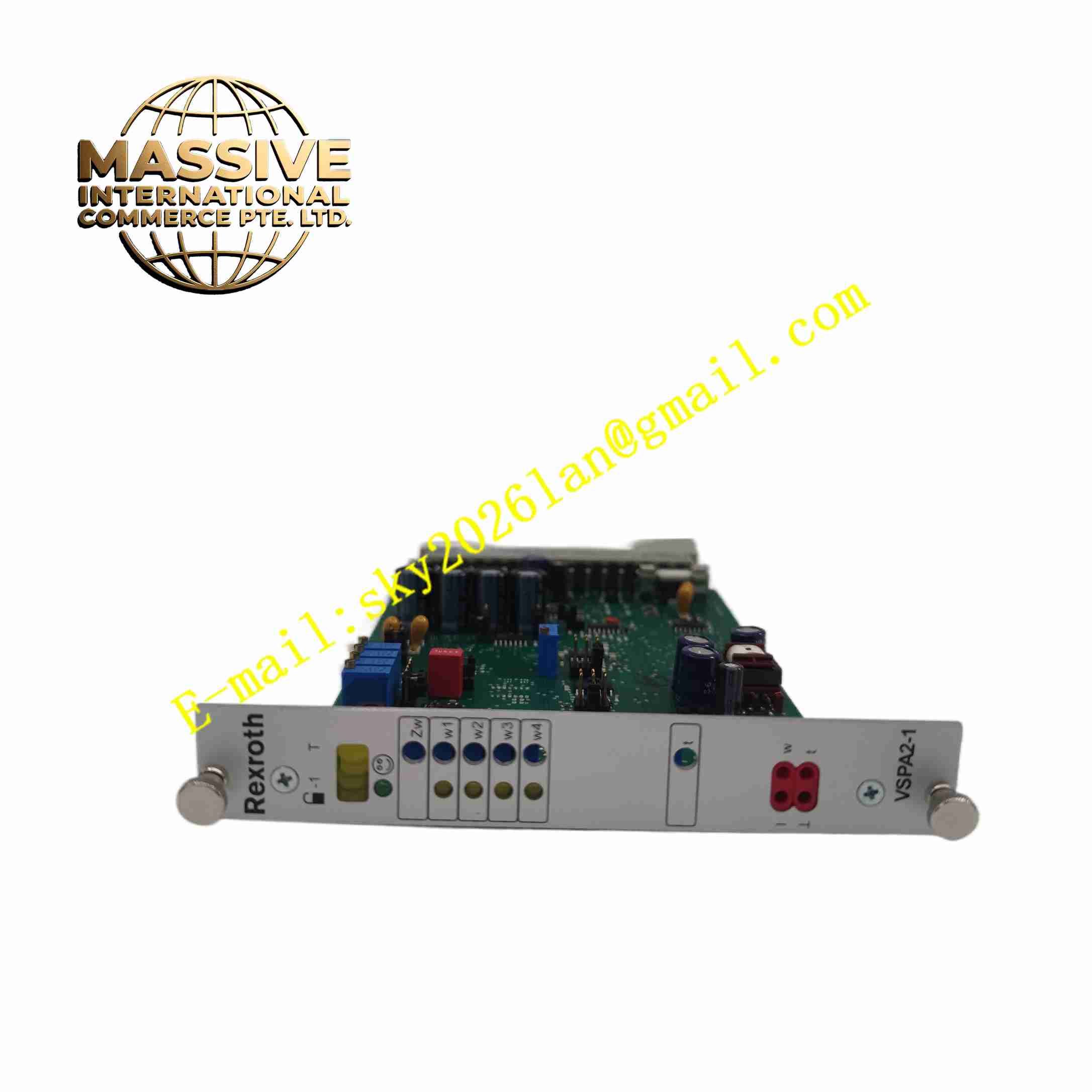
Description
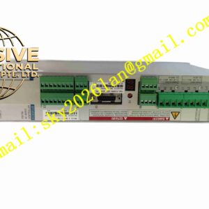
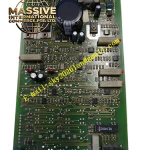
Rexroth R901002090 VT-VSPA2-1-2X/V0/T1
Technical Specifications
- Brand: Bosch Rexroth
- Material Number: R901002090
- Model: VT-VSPA2-1-2X/V0/T1
- Product Type: Analog proportional valve amplifier
- Component Series: 2X
- Board Format: Eurocard 100 mm x 160 mm, DIN 41494
- Connector: 48-pin multi-pin connector, DIN 41612, design F
- Supply Voltage: 24 V DC
- Differential Voltage Input: ±10 V, ±2 percent, maximum 2 mA
- Additional Voltage Input: ±2.5 V, ±2 percent, maximum 2 mA
- Current Input: 4 to 20 mA
- Command Value Inputs: 4 selectable ±10 V inputs
- Output Current per Solenoid: Maximum 2.5 A
- Chopper Frequency: Approximately 170 Hz to 410 Hz depending on valve type and operating point
- Operating Temperature: 0 °C to 50 °C
- Storage Temperature: -25 °C to +85 °C
- Net Weight: Approximately 0.17 kg
- Backplane Material: UL 94 V-0 recognized
Functional Features
- Differential ±10 V command value input.
- Four selectable command value inputs for different operating modes.
- 4 to 20 mA current input support.
- Command value signal polarity reversal via 24 V input or jumper.
- Ramp time selection via quadrant recognition or ramp time call-up with option T5.
- Adjustable ramp time range via jumper.
- Characteristic curve correction through adjustable step levels and maximum values.
- Enable input for safe output activation.
- Ramp on/off input for fast response when required.
- Ready for operation output signal.
- Switchable measuring sockets for T1 variant.
- Short-circuit protected power output stage.
- Overcurrent monitoring for output stage protection.
- Reverse polarity protection for the supply voltage.
- DC/DC converter power supply without raised zero point.
Application Scenarios
- Control of proportional directional valves 4WRA 6-2X and 4WRA 10-2X.
- Control of proportional directional valves 4WRZ-7X.
- Control of proportional pressure valves 3DREP 6-2X.
- Hydraulic system pressure regulation.
- Flow control in industrial hydraulic circuits.
- Mobile and stationary hydraulic equipment.
- Test bench hydraulic control.
- Machine tool hydraulic actuation.
- Process control systems requiring proportional valve drive.
Performance Parameters
- Maximum solenoid output current of 2.5 A per channel.
- Command value input range of ±10 V with ±2 percent accuracy.
- Current input range of 4 to 20 mA.
- Ramp time adjustable via internal potentiometer and external signals.
- Chopper frequency adapted to valve type and supply voltage.
- Output stage short-circuit protection.
- Overcurrent fault detection.
- Ready signal for system integration.
- Operating temperature range from 0 °C to 50 °C.
Material Composition
- Industrial-grade printed circuit board assembly.
- Electronic components including operational amplifiers, transistors, and power output stages.
- Potentiometers for ramp time, step level, and maximum value adjustment.
- DIN 41612 type F connector contacts.
- LED indicators for status display.
- Metal and plastic mechanical components for Eurocard mounting.
- UL 94 V-0 recognized board material.
Structural Features
- Eurocard format 100 mm x 160 mm.
- 48-pin DIN 41612 type F connector.
- Front-panel adjustment potentiometers.
- LED indicators for enable status, command value selection, and polarity.
- Measuring sockets for signal verification.
- Jumper settings for ramp time range and signal polarity.
- Compact single-card installation in standard amplifier racks.
- Clear labeling for inputs, outputs, and adjustment functions.
Working Principle
The VT-VSPA2-1 amplifier receives an analog command signal through its differential voltage input, current input, or one of four selectable command value inputs. The signal is conditioned, limited, and processed through a ramp generator to prevent abrupt valve movement. The processed command value drives a chopper-controlled power output stage that supplies proportional current to the valve solenoid. The output stage monitors current and shuts down in case of overcurrent or missing enable signal. The ready output indicates normal operation, while measuring sockets allow verification of internal signals during commissioning and maintenance.
Installation Requirements
- Install the amplifier card into a compatible Eurocard rack or subrack.
- Connect the 48-pin DIN 41612 type F connector securely.
- Supply 24 V DC with correct polarity.
- Connect the proportional valve solenoid to the designated output terminals.
- Wire command value inputs according to the required control mode.
- Set jumpers for polarity, ramp time range, and enable behavior.
- Adjust ramp time, step levels, and maximum values during commissioning.
- Ensure adequate ventilation within the amplifier rack.
- Verify the ready signal before enabling valve operation.
- Keep signal wiring separate from high-power cables to reduce interference.
Precautions for Use
- Do not exceed the 2.5 A maximum output current per solenoid.
- Do not adjust sealed potentiometers beyond the specified range, as this may affect warranty.
- Verify valve compatibility with the VT-VSPA2-1 amplifier before commissioning.
- Ensure the supply voltage remains within the specified 24 V DC range.
- Do not operate the amplifier outside the 0 °C to 50 °C temperature range.
- Check wiring polarity before energizing the amplifier.
- Use the enable input for safe system integration.
- Perform functional tests after installation and after parameter changes.
- Refer to the official Bosch Rexroth documentation RC 30110 for detailed wiring and adjustment procedures.