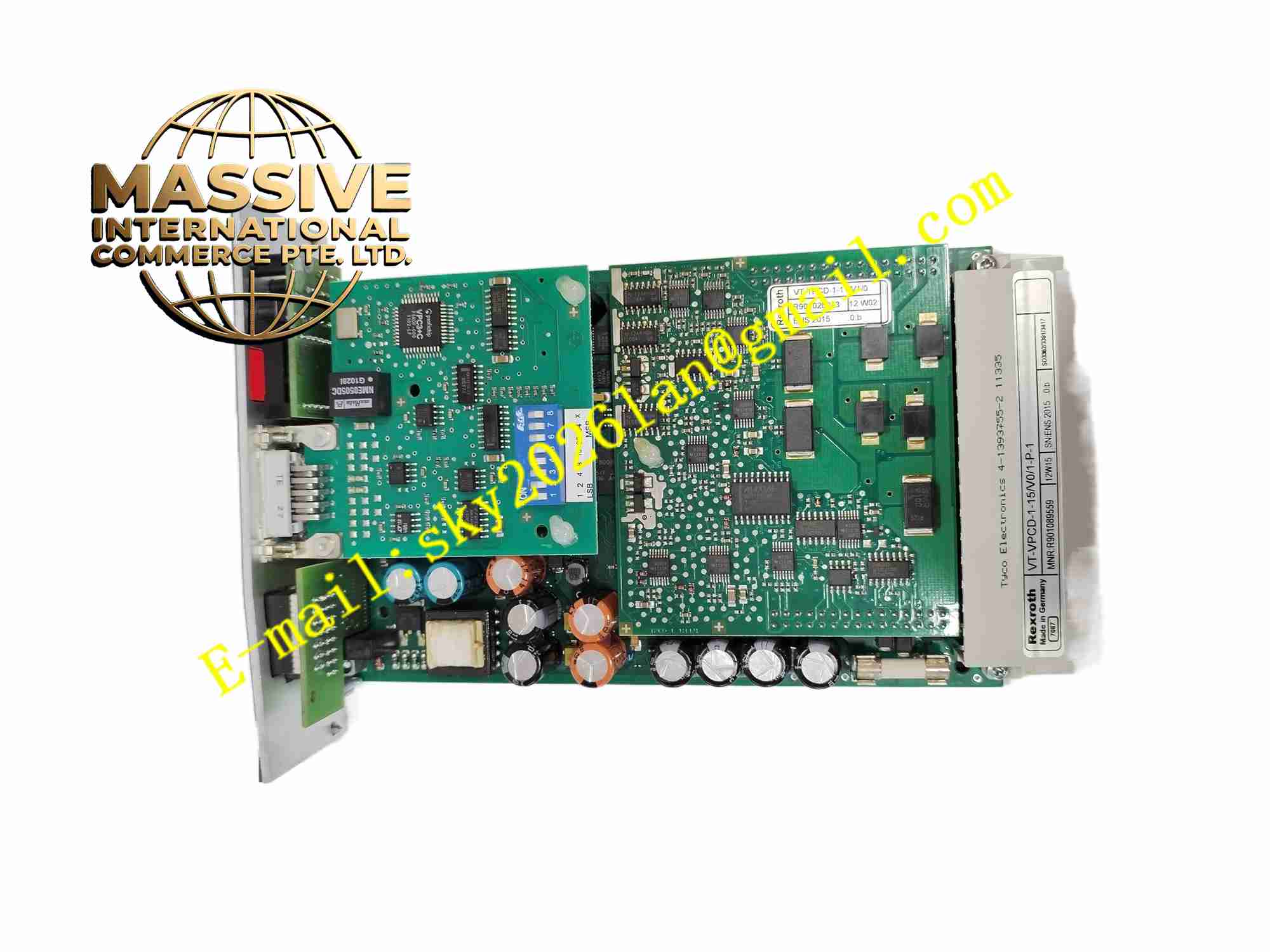
Description
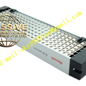
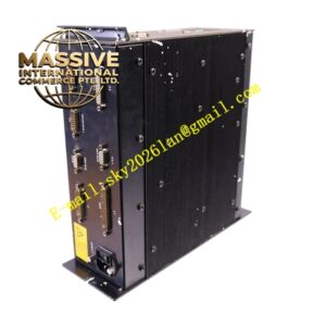
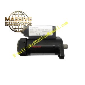
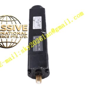
Rexroth VT-VPCD-1-16V01-P-1 R901089559
Technical Specifications: Part number: R901089559 Power supply: 24VDC Control output: ±10V analog signal for proportional valve drive Feedback input: LVDT, potentiometer, 4-20mA, ±10V analog feedback Control modes: Position, velocity, force/pressure closed loop Communication: Serial service interface for parameter setup Operating temperature: 0℃ to +55℃ Protection class: IP20 when installed in cabinet Mounting: Plug-in card for Rexroth control rack
Functional Features: Digital closed-loop control for single electro-hydraulic axis. Multiple selectable control modes for position, speed and force regulation. Support various types of position and pressure feedback sensors. Analog output signal to drive hydraulic proportional valves. Parameter configurable gain, ramp and limit via service software. Continuous monitoring of feedback signal and hardware status. Fault output relay for external alarm when signal loss or hardware fault detected. Signal filtering to suppress noise from hydraulic sensor wiring.
Application Scenarios: Hydraulic press machine axis control, metal forming equipment, injection molding machine hydraulic axis, material test bench hydraulic actuator control, steel mill hydraulic positioning system, heavy duty hydraulic lifting equipment.
Performance Parameters: High resolution digital closed-loop calculation. Fast response for hydraulic axis dynamic regulation. Configurable control parameters to match different hydraulic actuator characteristics. High stability under heavy load and impact load conditions.
Material Composition: FR4 high precision industrial printed circuit board. 16-bit ADC and DAC conversion chips. Analog signal conditioning operational amplifiers. Microprocessor for control algorithm calculation. Flame retardant plastic front panel. Gold-plated edge connector for rack backplane connection. Screw terminal block for sensor and valve wiring.
Structural Features: Standard Eurocard plug-in board form factor. Front panel with LED indicators for power, run and fault. Edge connector connects to rack backplane for power and auxiliary signals. Screw terminal block on front panel for field sensor and proportional valve wiring. Onboard jumper switches for basic hardware configuration. Internal separation between low level feedback signal circuit and valve drive output circuit.
Working Principle: 24VDC power supplies the controller card. Setpoint command from upper controller and feedback signal from hydraulic actuator sensor enter the card. The microprocessor executes closed-loop control algorithm, calculates deviation between setpoint and actual feedback value, generates output command. Analog circuit converts digital command into ±10V analog signal to drive proportional hydraulic valve. The valve controls hydraulic flow and pressure to move hydraulic cylinder. The card continuously monitors feedback signal quality and hardware state, triggers fault alarm when signal breaks or hardware abnormality appears.
Installation Requirements: Insert the card into matching slot of Rexroth control rack. Use shielded twisted pair cable for sensor and proportional valve wiring. Separate analog signal cables and high power hydraulic power cables. Tighten all terminal screws to specified torque. Install inside IP20 rated electrical cabinet. Connect protective earth wire for rack chassis.
Usage Notes: Download and save all axis parameters before card replacement. Match feedback sensor type in parameter configuration. Check wiring polarity of LVDT or position sensor after installation. Cut off rack power before inserting or removing the controller card. Verify closed-loop stability and limit protection during commissioning. Do not modify circuit components on the board.