



Description
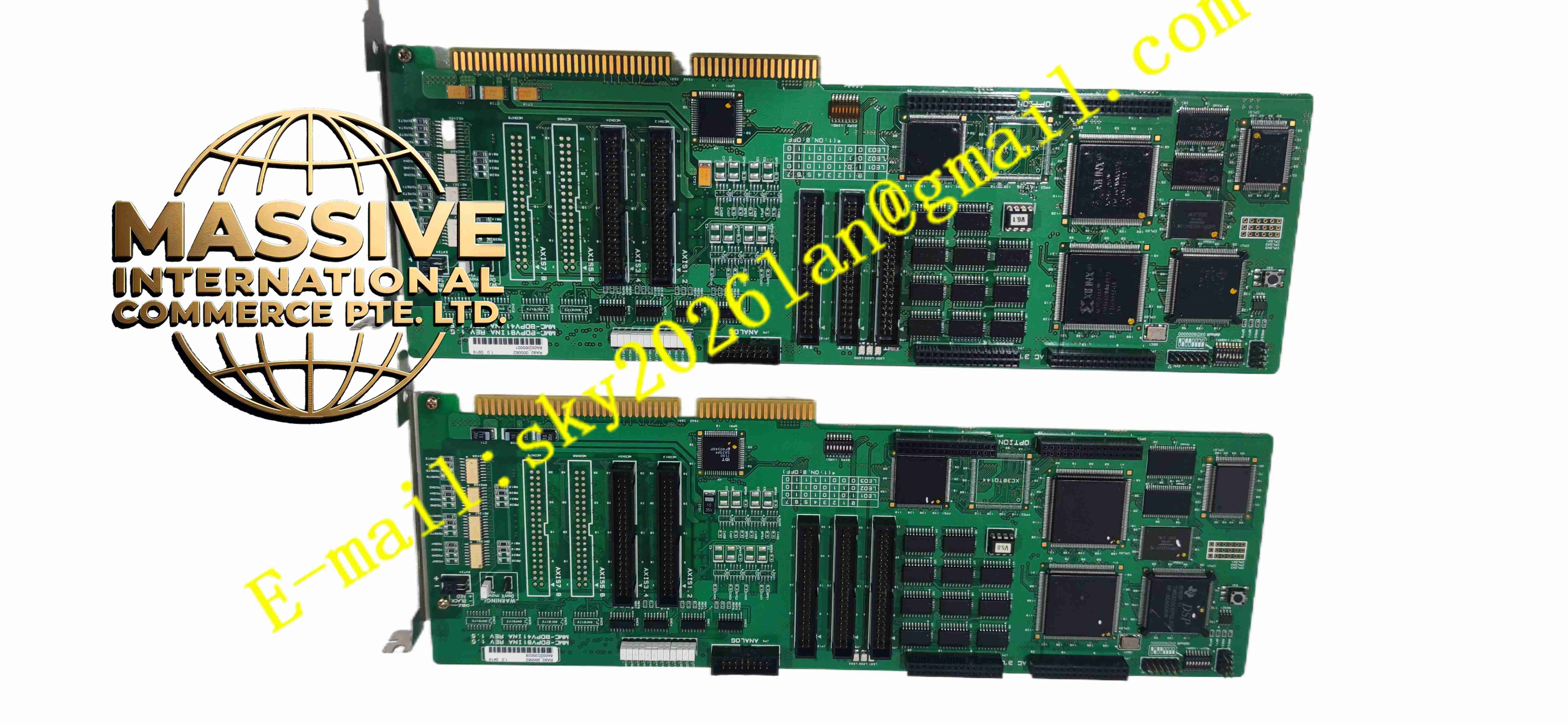
Rockwell MMC-BDPV41INA(8B15D60024A)
Technical Specifications Multi-axis motion control capacity; differential pulse and direction signal output; digital input and output channels; PCI or industrial backplane bus interface; non-volatile memory for motion recipe storage; hardware position counter; rack mounting.
Functional Features Linear and circular multi-axis interpolation; electronic cam and electronic gear function; hardware position latch and position capture; programmable digital input/output for machine interlock; motion trajectory buffer for continuous movement; hardware watchdog for system reset; fault diagnosis and position error monitoring.
Application Scenarios High-speed packaging machinery; printing and converting line; automated assembly equipment; CNC special machine; material cutting and profiling machine.
Performance Parameters Operating ambient temperature 0℃ to +55℃; storage temperature -40℃ to +85℃; relative humidity 5% to 90%, no condensation; industrial EMC anti-interference compliance.
Material Composition Multi-layer industrial PCB; high-performance motion control FPGA chip; flash memory and RAM chips; differential line driver and receiver chips; gold-plated bus connectors; LED status indicators; surge suppression components.
Structural Characteristics Standard plug-in board form factor; rear gold finger for host bus connection; front panel terminal connectors for servo pulse signal and digital I/O wiring; internal circuit layout separates high-speed motion signal and digital logic circuit.
Working Principle Host system downloads motion program and recipe parameters to control board memory. FPGA hardware generates high-speed pulse/direction motion commands and sends to servo drives. Encoder feedback signal returns to on-board counter for closed-loop position comparison. Digital I/O channels read machine interlock signal and output control signal according to motion program logic.
Installation Requirements Power off host rack before inserting control board. Insert board into matching bus slot and secure fixing screw. Connect shielded differential signal cables to servo drives. Download motion project and configure axis parameters. Complete cabinet protective earthing and test each axis movement.
Usage Notes Use shielded twisted pair cable for pulse and encoder wiring. Keep signal cable separated from high power AC wiring. Backup motion recipe before hardware replacement. Do not hot swap board while host system running.



