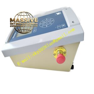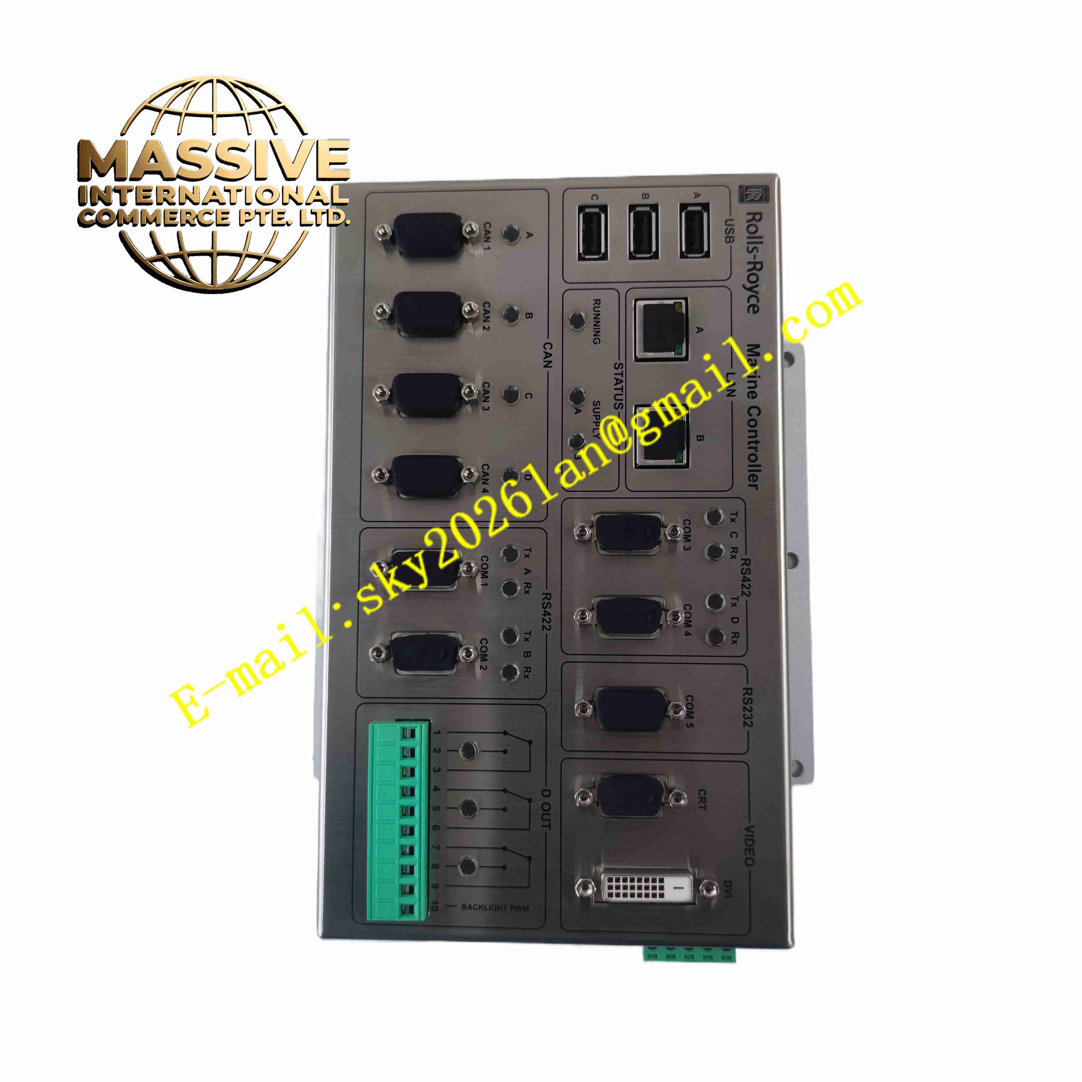
Description
ROLLS-ROYCE H1111.0103
Technical Specifications
- Product Type: Turbine control PCB assembly
- Power Supply: 24 V DC
- Signal Type: Analog input 4-20 mA, thermocouple / RTD temperature signal, 24 V DC discrete I/O
- Bus Interface: Rolls-Royce proprietary turbine control backplane bus
- Diagnostic Functions: Wire break, short circuit and channel self-test
- Protection Rating: Board assembly IP00, installed inside sealed control cabinet IP20
- Operating Temperature: 0 °C to +60 °C
- Mounting: Plug-in rack slot module
- Cooling: Passive convection cooling
Functional Features
- Multi-channel analog signal conditioning for turbine pressure, temperature and flow transmitters.
- Discrete signal input collects limit switch, valve feedback and protection relay status.
- Digital output drives turbine auxiliary relays and local indicator lamps.
- Galvanic isolation separates field turbine sensor circuit and turbine control backplane bus.
- Continuous per-channel diagnostic detects wiring break and short circuit fault.
- Conformal coated PCB withstands power plant cabinet humidity and dust environment.
- Front panel LED indicators display channel power and fault status.
- Fault event data transmits to turbine main controller for sequence of event recording.
- Overvoltage and reverse polarity protection protects internal circuit from field surges.
- Hot-swap capable for replacement during planned maintenance shutdown.
Application Scenarios
- Marine gas turbine control cabinet signal conditioning board
- Industrial heavy gas turbine governor I/O signal interface
- Combined cycle power plant turbine protection rack
- Offshore platform gas turbine auxiliary control system
- Turbine fuel valve feedback and interlock signal acquisition
Material Composition
- Main PCB: FR4 high reliability printed circuit board with conformal coating
- Signal processing components: Instrumentation amplifiers, analog multiplexers
- Logic components: Industrial digital logic chips
- Isolation components: High speed optocoupler chips
- Backplane connector: Gold-plated copper edge contact pins
- Passive components: Precision metal film resistors and capacitors
Structural Characteristics
- Rectangular plug-in rack module PCB with front panel handle and locking lever.
- Front panel equipped with LED indicators for module and channel diagnostic state.
- Rear gold-plated edge connector inserts into turbine control rack backplane bus.
- Each signal channel has independent isolation and signal conditioning circuit.
- Internal circuit layout separates low level analog sensor circuit and high power discrete drive circuit.
- Conformal coating fully covers PCB surface to resist moisture and airborne contaminants.
Working Principle Field sensor signals including temperature, pressure and valve feedback enter H1111.0103 input terminals. Analog signal conditioning circuit amplifies, filters and compensates raw sensor signals. Discrete input circuit reads 24 V DC contact status. Processed signal data transmits to turbine main controller via rack backplane bus. When controller sends output command, the board drives discrete relay outputs to actuate auxiliary equipment. Channel diagnostic circuit monitors loop impedance continuously and reports fault to turbine controller.
Installation Requirements
- Insert H1111.0103 board into designated slot of Rolls-Royce turbine control rack.
- Use shielded twisted pair cable for turbine field sensor and valve feedback wiring.
- Separate turbine signal cables from high power generator and motor cables.
- Complete protective earth connection for rack and control cabinet.
- Verify wiring polarity of all analog and discrete field devices.
- Perform channel signal test and fault simulation test after wiring completion.
- Inspect backplane connector contact integrity before power energization.
Usage Notes
- Follow turbine control system maintenance manual for hot swap operation.
- Do not apply voltage exceeding rated specification to input and output terminals.
- Keep cabinet dry and free of oil mist, conductive dust and corrosive gas.
- Execute periodic proof test for turbine signal channels.
- Disconnect field wiring before high voltage insulation resistance test.
- Use anti-static wristband and anti-static mat when handling spare board.
- Replace board immediately when permanent signal acquisition or drive fault occurs.