Description
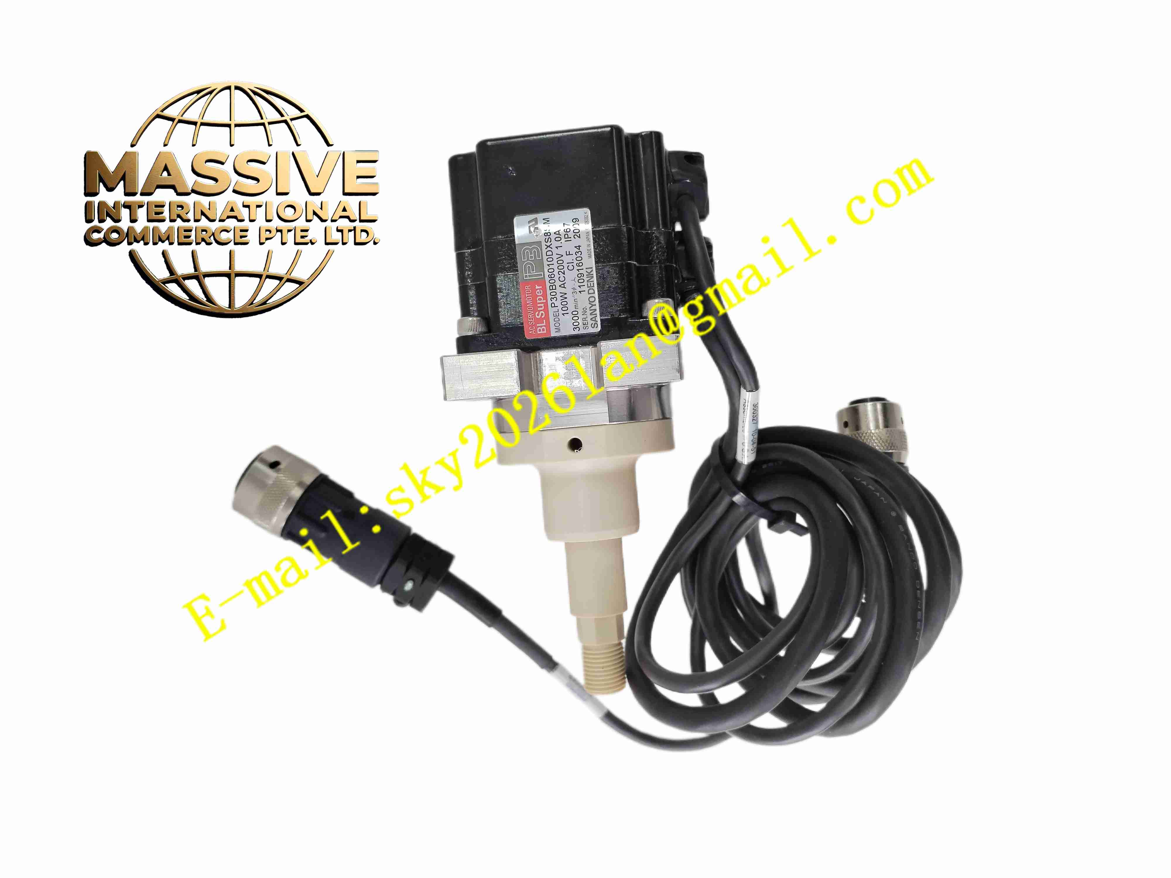
Sanyo Denki P30B06010DXS8SM
Technical Specifications: Series: BL Super P30 series servo motor Rated output power: 100W Rated voltage: 200V AC Rated speed: 3000 rpm Rated torque: 0.32 N·m Maximum torque: 0.96 N·m Encoder type: Incremental encoder Built-in component: Electromagnetic holding brake Flange dimension: 60mm square flange Shaft type: Solid round shaft Operating temperature range: -10℃ ~ +40℃ Storage temperature range: -20℃ ~ +80℃ Relative humidity: 5% to 85%, non-condensing Protection grade: IP65 for motor housing
Functional Features: Medium inertia rotor design, suitable for driving mechanical load with larger inertia. Integrated incremental encoder provides high precision speed and position feedback. Built-in electromagnetic holding brake locks shaft position under power loss condition. High torque density inside compact 60mm flange housing. Low torque ripple to guarantee smooth rotation under low speed working condition. High overload capability for short duration acceleration and deceleration. Sealed housing structure prevents dust and splashing liquid entering internal components. Standard industrial connectors for motor power cable and encoder feedback cable.
Application Scenarios: Automated material handling mechanism, medium size packaging machine, CNC small machine tool feed axis, printing equipment positioning roller, automatic cutting machine, conveyor indexing actuator, industrial robot auxiliary joint axis.
Performance Parameters: Smooth rotation at low speed with small torque fluctuation. Fast response for position closed loop control with medium inertia load. Brake maintains rated static holding torque continuously after power loss. Continuous operation: 24 hours stable operation under rated load range. Strong overload capacity for short time peak torque output during acceleration.
Material Composition: Motor housing: Die cast aluminum alloy with black anti-corrosion surface coating. Rotor: Silicon steel lamination stack embedded with sintered neodymium permanent magnet. Stator: Copper enameled wire wound stator iron core. Output shaft: High strength quenched alloy steel. Encoder casing: High precision flame retardant plastic. Brake assembly: Electromagnetic coil, friction disc and pressure spring set. Connector housing: PA66 flame retardant plastic with metal shielding shell.
Structural Features: Cylindrical motor body with 60mm square mounting flange. Front solid output shaft with keyway for coupling connection. Internal layout separated into stator winding chamber, permanent magnet rotor chamber, brake assembly chamber and encoder chamber. Dual precision ball bearings support rotor high speed rotation. Rear end fitted with power connector and encoder signal connector. Encoder mechanically coupled to rotor shaft for synchronous position measurement. Rubber sealing gaskets installed between front and rear housing covers.
Working Principle: Three-phase AC current output from servo amplifier flows into stator winding of servo motor. Alternating magnetic field produced by stator interacts with permanent magnet rotor and generates electromagnetic torque to rotate motor shaft. Incremental encoder at motor rear end continuously samples rotor angular position and rotation speed, and transmits pulse feedback signal back to servo drive. Servo drive compares feedback position value with target position command, adjusts stator current magnitude and phase to eliminate position error. When power supply fails, brake coil de-energizes, spring pushes friction disc to clamp rotor shaft and lock rotation to prevent load slipping.
Installation Requirements: Power off servo amplifier before motor installation and wiring work. Fix 60mm square flange on equipment rigid mounting base with specified bolts. Connect motor power cable and encoder shielded cable to corresponding connectors. Install flexible coupling between motor shaft and mechanical load shaft. Adjust coupling to reduce shaft radial and axial misalignment. Reserve air circulation space around motor housing for heat dissipation. Ensure motor mounting base flat and rigid to reduce operating vibration. Connect motor protective earth terminal to reliable protective grounding point.
Usage Notes: Avoid impact and hammer force applied directly on motor shaft during installation. Do not exceed rated continuous torque and peak torque specification. Use shielded servo cables and separate servo wiring from high voltage power cables. Brake only used for static shaft holding, not for dynamic emergency stop braking. Regularly inspect connector tightness and cable outer sheath damage. Do not operate motor beyond rated temperature and humidity range. Prevent metal chips, cutting fluid and corrosive liquid splash on motor housing.