Description
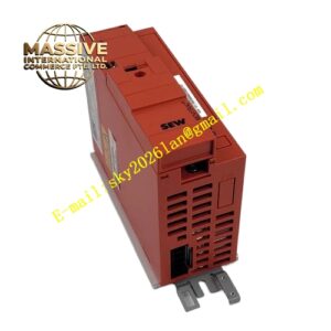
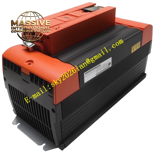
SEW MC07B0220-503-4-00
Technical Specifications: Rated motor power: 22kW Three-phase input voltage: 380VAC – 500VAC Control mode: VFC open-loop flux vector control Built-in brake chopper Protection class: IP20 Ambient operating temperature: 0℃ ~ +45℃ Cooling method: Forced air cooling
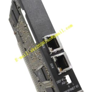
Functional Features: Vertical installation inside electrical cabinet via screw fixing IP20 protection grade only for cabinet interior Integrated protection functions: overcurrent, overvoltage, undervoltage, overtemperature, earth fault and short-circuit protection Multi-channel digital and analog I/O terminals Automatic motor parameter identification Multi-section speed selection function Analog speed reference input via voltage or current signal Relay contact for fault signal output Supports optional fieldbus communication expansion cards Built-in fan speed monitoring function
Application Scenarios: Heavy load conveyor main drive Large fan and water pump energy saving control Mixing machine main drive Crane auxiliary speed regulation Large material handling equipment transmission
Performance Parameters: Output frequency range: 0Hz ~ 500Hz Overload capacity: 150% rated current for 60 continuous seconds Open-loop VFC speed control accuracy ±0.5% Adjustable acceleration and deceleration ramp
Material Composition: Thickened cold rolled steel sheet housing with powder coating anti-corrosion treatment High-power multi-layer industrial PCB main control board Large power IGBT power module NTC temperature monitoring sensor Thick copper high-current power terminals Flame-retardant plastic insulating brackets Large capacity DC bus electrolytic capacitors Metal heat sink assembly
Structural Characteristics: Vertical heavy-duty cabinet mounting structure with multiple screw fixing holes Front panel equipped with multi LED indicators for running, fault and fan state Main high-power circuit terminals on upper part, control signal terminals on lower part Built-in large heat sink and high-speed cooling fan Side reserved space for communication expansion card installation Physical separation between power cavity and signal cavity to reduce electromagnetic interference
Working Principle: Three-phase alternating current is rectified into DC bus voltage by internal rectifier bridge. High power IGBT module converts DC voltage into adjustable three-phase AC to drive asynchronous motor. VFC open-loop flux vector control calculates output voltage and frequency according to speed setpoint without rotor feedback. Regenerative energy during motor deceleration passes built-in brake chopper and dissipates on external brake resistor. Temperature sensor monitors heat sink temperature. Once fault occurs, hardware circuit cuts off power output and stores fault code.
Installation Requirements: Vertical upright installation inside closed electrical cabinet, inverted installation forbidden Reserve large ventilation space for heat dissipation, air inlet and outlet cannot be blocked Power cables and control signal cables must be laid in separate cable ducts Input three-phase voltage must conform to nameplate specification Installation environment must avoid dust, moisture and corrosive gas PE earth terminal must be reliably connected with ground busbar
Precautions for Use: Wait at least 15 minutes after power off to complete capacitor discharge before opening cover for maintenance Confirm three-phase input voltage before power-on Complete motor identification in commissioning stage Capacitors cannot be connected in parallel at output terminals Regularly clean cooling fan and heat sink dust Short-circuit of brake terminals is strictly prohibited Check tightness of high-current power terminals periodically