Description
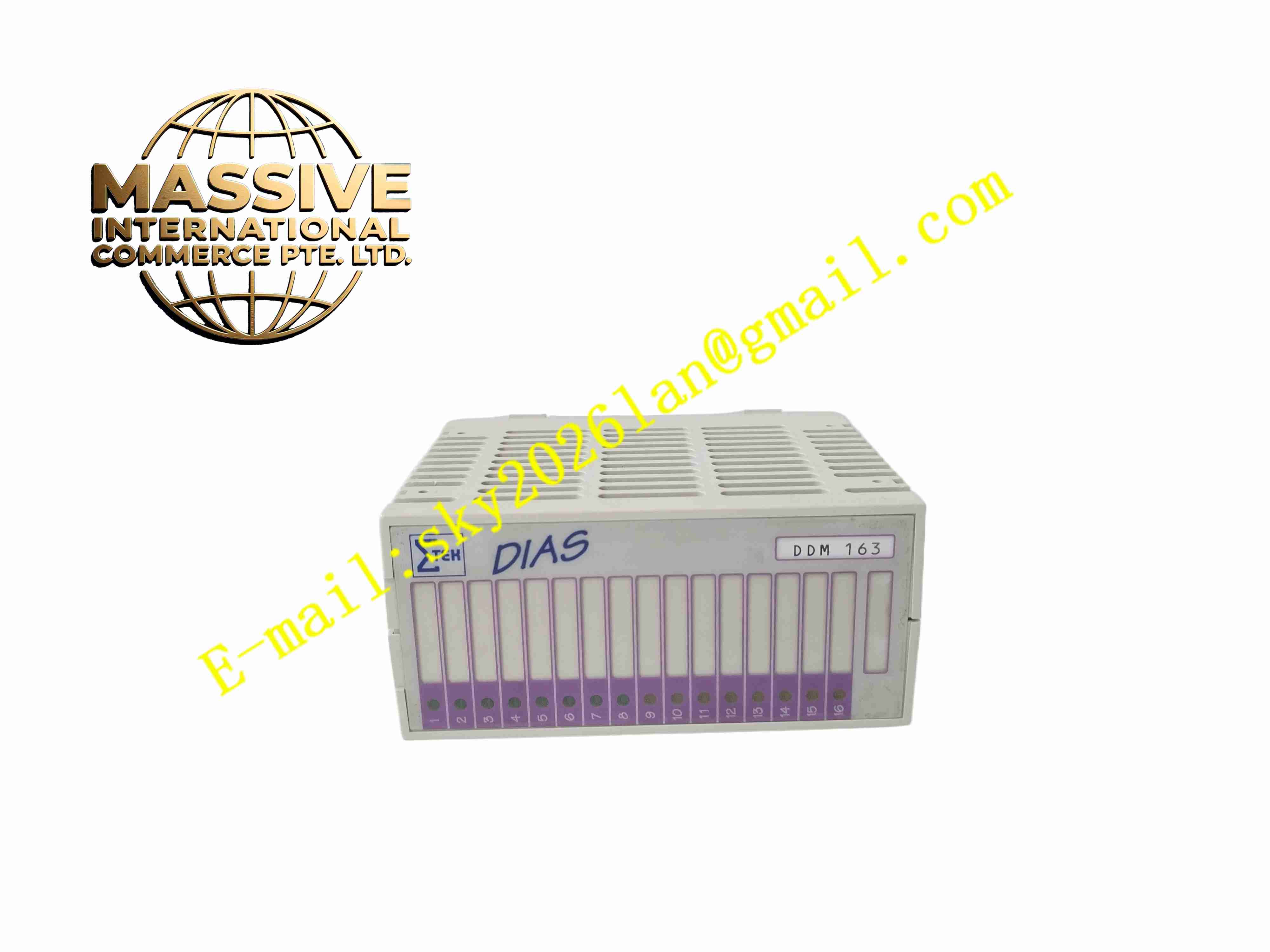
SIGMATEK DDM163
Technical Specifications 24 V DC backplane power supply; multiple 24 V DC opto-isolated digital inputs; short-circuit protected digital outputs rated 24 V DC; per-channel LED status indication; DIAS backplane bus interface; input filter time configurable in software; operating temperature 0 °C to +60 °C; rack plug-in DIAS form factor.
Functional Features Optical isolation separates field 24 V circuits from the DIAS controller backplane; configurable input debounce filtering for mechanical contacts; hardware short-circuit and overload shutdown for output channels; per-channel status reporting to the CPU; channel fault diagnosis for overcurrent events.
Application Scenarios Packaging machinery discrete sensor collection, conveyor system solenoid and indicator lamp control, woodworking machine safety interlock signal acquisition, textile machine auxiliary actuator control.
Material Composition Flame-retardant plastic module housing; FR4 I/O PCB; optocoupler isolation chips; output power switching semiconductors; gold-plated backplane edge connector; removable screw terminal blocks for field wiring.
Structural Characteristics Horizontal DIAS rack plug-in module; front panel with per-channel LED indicators and detachable field terminal block; rear gold finger connector mates with Sigmatek DIAS backplane; isolation barrier separates field 24 V ground and control logic ground.
Working Principle Field 24 V sensor signals pass optocoupler isolation and configurable debounce filters before being sampled by the module logic circuit. The module transmits input states to the DIAS CPU over the backplane bus. Output commands from the CPU enable power switches to drive field 24 V loads, and protection circuits cut off channels during short-circuit conditions.
Installation Requirements Insert the module only into de-energised DIAS rack; connect proximity switches and solenoid loads to corresponding terminal channels; set input filter time in LASAL engineering software; separate field digital wiring from high-frequency inverter power cables.
Operation Notes Disable relevant output channels before maintenance on field actuators; check LED channel status during commissioning to identify open or short wiring faults; confirm field 24 V supply polarity before energising the I/O module.