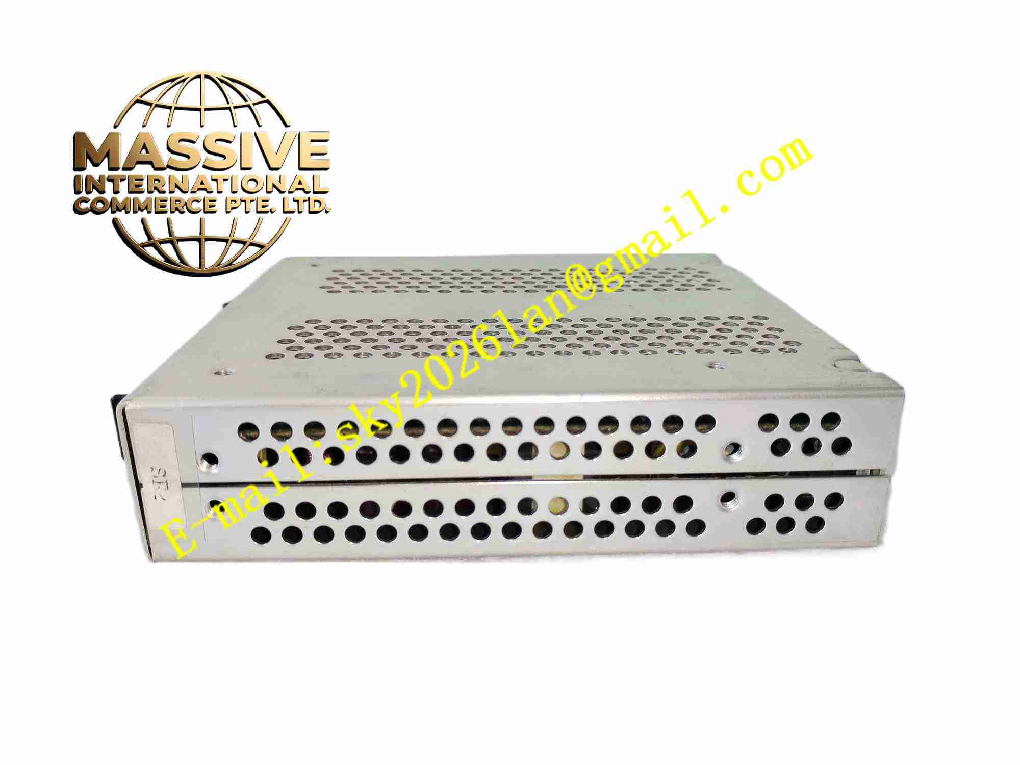
Description
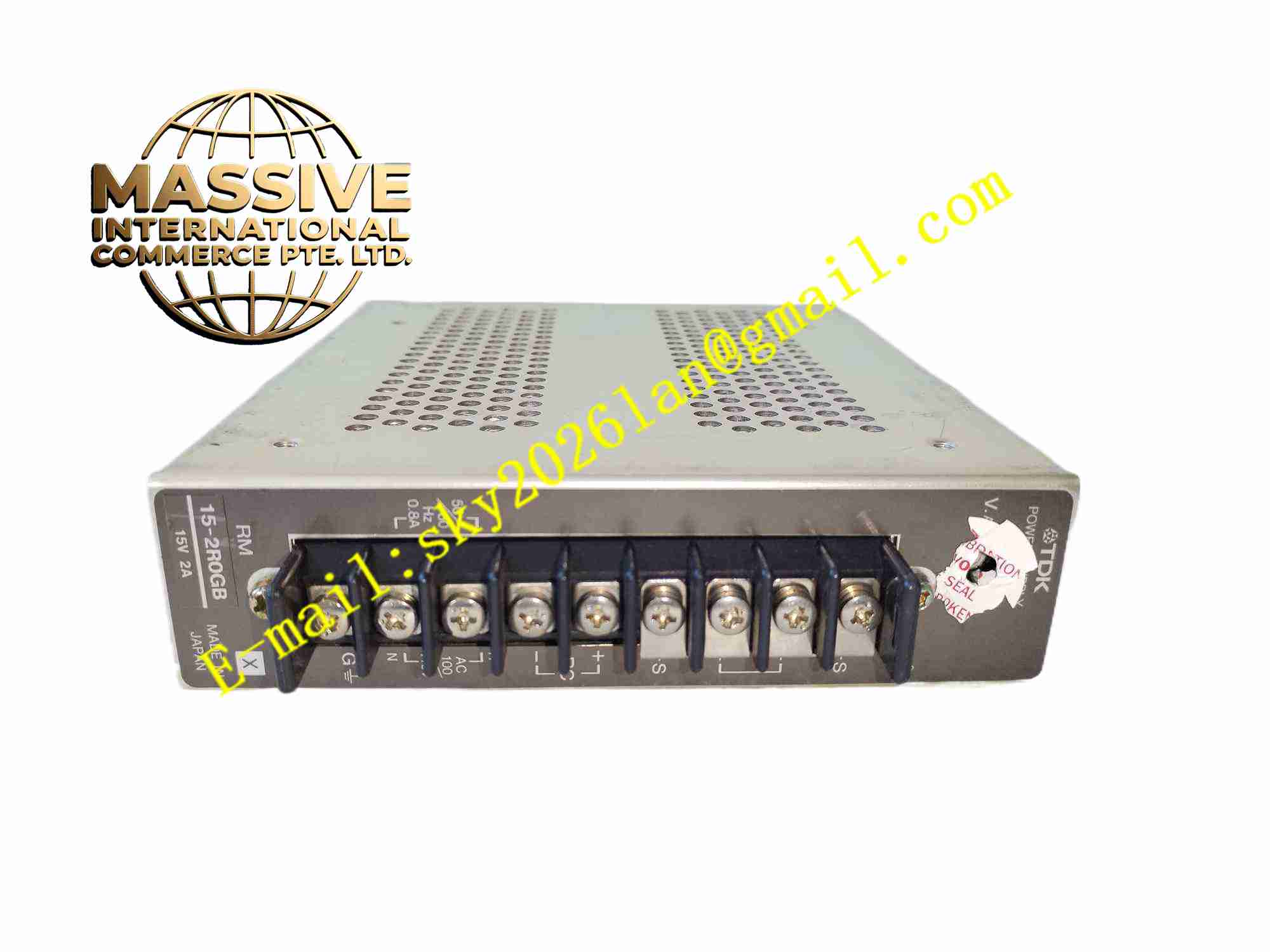
TDK-Lambda RM15-2R0GB
Technical Specifications
- Product type: Isolated DC-DC converter module
- Input voltage: 9V to 36V DC
- Output voltage: 2.0V DC
- Output power: 15W
- Output current: Max 7.5A
- Isolation voltage: 1500V DC
- Efficiency: Up to 87%
- Operating temperature: -40 °C to +85 °C
- Storage temperature: -55 °C to +125 °C
- Humidity: 5% to 95%, non-condensing
- Mounting: Through hole soldering on PCB
- Protection: Over current, over voltage, over temperature, short circuit protection
- Certification: CE, UL safety certification
Functional Features
- Wide DC input voltage range
- Fixed 2.0V regulated output
- 1500V DC isolation between input and output
- High conversion efficiency
- Complete set of fault protection functions
- Remote on/off control pin
- Low output ripple and noise
- Brick style compact package
- No internal electrolytic capacitor
- Stable operation under wide temperature range
Application Scenarios
- Industrial control board local power supply
- Telecommunication embedded equipment power conversion
- Automated test instrument internal power
- Railway electronic auxiliary circuit
- Medical non-safety related embedded board power
Materials and Construction
- Package: Metal alloy encapsulated brick housing
- PCB: Internal high frequency FR4 substrate
- Magnetic components: Shielded high frequency transformer and inductor
- Semiconductors: High speed power MOSFET
- Potting compound: Thermally conductive epoxy resin
- Pins: Tin plated copper through-hole pins
Structural Features
- Standard brick rectangular encapsulated module
- Through-hole pins arranged on one edge for PCB soldering
- Internal circuit fully potted with thermally conductive epoxy
- Metal shell for heat dissipation and electromagnetic shielding
- Internal high frequency transformer providing galvanic isolation
- Compact sealed structure resistant to vibration and dust
Working Principle DC input voltage feeds into high frequency switching circuit. The high frequency transformer isolates input side and output side. Rectifier and filter circuit on secondary side generate stable 2.0V DC output. Closed loop feedback circuit continuously samples output voltage and adjusts switching duty cycle to maintain constant output voltage. When fault condition occurs, internal protection circuit shuts down switching operation to protect module and load.
Installation Requirements
- Solder module pins onto host PCB following pad layout specification
- Add external input and output capacitors close to module pins
- Maintain proper thermal contact for heat dissipation at high load
- Keep ambient temperature within -40 °C to +85 °C
- Connect remote on/off pin according to system logic requirement
- Keep input and output wiring trace short to reduce noise
Precautions
- Do not reverse input voltage polarity
- Do not exceed maximum output current rating
- Module surface reaches high temperature during full load operation
- Wear ESD protection before handling module
- Store spare modules in anti-static packaging
- Avoid mechanical stress on solder pins during assembly
- Prevent condensation in low temperature high humidity environment