Description
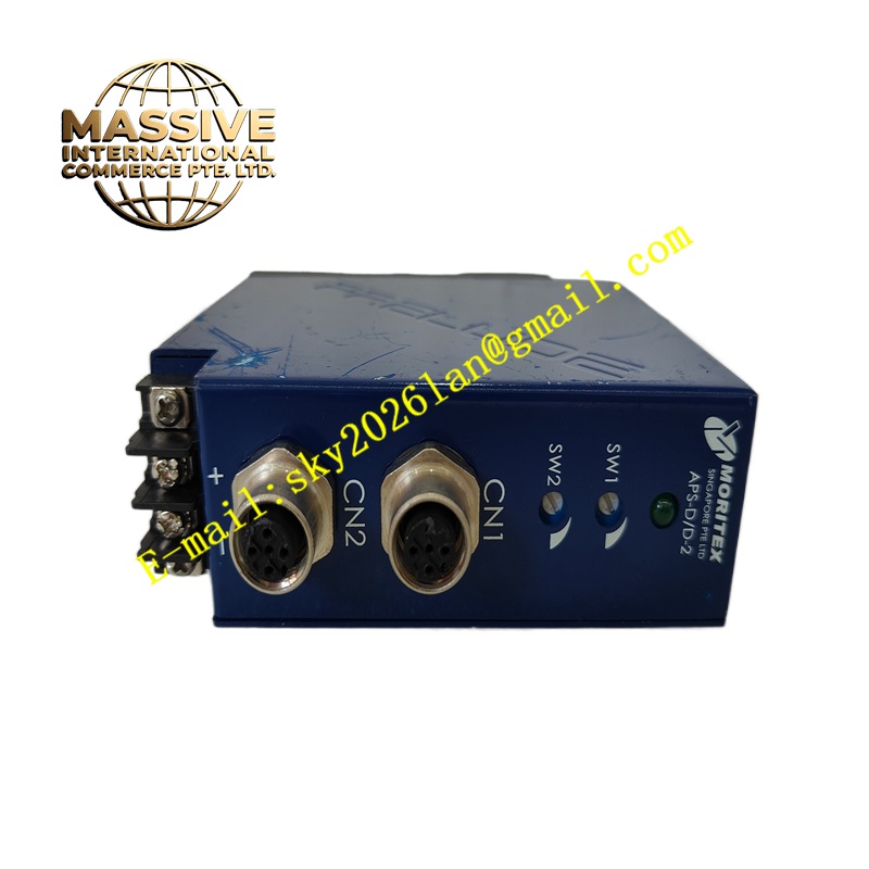
Techsoft APS-DD-2
Technical Specifications Multi-channel digital and pulse input; opto-isolated input channels; support dry contact and 24V DC signal; pulse counting function; 24V DC module power supply; operating temperature 0°C to +60°C; IP20 protection; configurable input filter time.
Functional Features Detect on-off status of field proximity switches, limit switches and pulse encoders. Filter bounce interference of mechanical contact signals. Count pulse signals and calculate frequency and speed values. Upload status data and counting results to host controller through communication interface. Report channel input fault and power abnormality. Support input polarity and filter parameter configuration via software.
Application Scenarios Conveyor belt speed measurement, material counting equipment, packaging machine position detection, logistics sorting equipment, automatic assembly line signal acquisition.
Performance Parameters Stable pulse counting under mechanical vibration; adjustable signal filtering time to eliminate contact bounce; high isolation strength for field signal circuit; low signal response delay.
Material Composition PCB substrate is FR-4 flame-retardant multilayer printed circuit board; logic and counting chips are industrial semiconductors; optocoupler devices provide channel isolation; outer housing is flame-retardant ABS plastic; terminal blocks use nickel-plated copper contacts.
Structural Characteristics DIN rail mounting rectangular plastic housing. Front panel equipped with channel status LED indicators. Top and bottom terminal blocks for 24V power supply, field signal input and communication wiring. Internal circuit divides isolation input area and core processing area.
Working Principle Field digital and pulse signals enter opto-isolation circuits, filter out bounce and high-frequency interference according to set filter parameters. The onboard processor identifies signal state and counts pulse edges, then transmits processed status and counting data to the host controller through the communication port.
Installation Requirements Mount the module on standard DIN rail inside the control cabinet. Wire 24V DC power and field sensor signals to corresponding terminals. Connect the communication cable to the host controller. Configure filter parameters and counting mode in supporting software. Test each input channel and pulse counting function after power-on.
Precautions for Use Separate sensor signal cables from high-power drive cables. Do not apply voltage exceeding 24V DC to input terminals. Keep the cabinet away from water and corrosive gas. Disconnect power before modifying wiring.