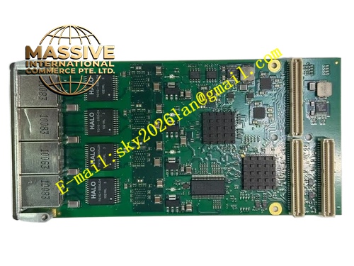
Description
TEWS Technologies TPMC917‑10R
Technical Specifications: PCI bus interface: 32‑bit, 33 MHz, 3.3 V / 5 V PCI signaling; SRAM memory capacity: 4 MByte organized as two banks of 512K × 32‑bit; serial ports: 4‑channel RS‑232 via DB25 female front‑panel connector; UART chip ST16C654, each channel equipped with 64‑byte transmit FIFO and 64‑byte receive FIFO; programmable baud rate range from 1200 bps up to 115.2 kbps; ESD protection ±15 kV human‑body model, ±6 kV IEC 61000‑4‑2; backup battery CR2430 lithium cell, nominal 2.6 V, typical service life 8‑year at 25 °C; power‑fail detection threshold 4.37 V typical; power consumption: +3.3 V 177 mA typical, +5 V 456 mA typical; operating temperature 0 °C‑70 °C; storage temperature ‑40 °C‑85 °C; humidity 10‑90 %RH non‑condensing; mechanical form factor single‑size PMC; weight 115 g; onboard DIP switch for battery source selection between onboard cell and external battery via P14 mezzanine connectorManualsLib.
Functional Features: Four hardware‑buffered RS‑232 channels support independent parameter configuration for baud rate, parity, data bits and stop bits; deep 64‑byte transmit and receive FIFO buffers lower host CPU interrupt overhead under high‑speed serial data streaming; automatic power‑fail switchover circuit transfers SRAM power supply to lithium battery within 1.5 μs upon main power collapse; battery monitoring circuit checks battery voltage every 24 hours and generates hardware interrupt when battery voltage drops below threshold; DIP‑switch configurable backup source selects internal lithium cell or external battery input; DB25 front‑panel connector brings all serial signals outside host chassis without custom cabling; full PCI 2.1 compliance guarantees interoperability with standard PMC carrier boards; ESD protection diodes safeguard serial ports against electrostatic discharge damage on factory floors.
Application Scenarios: Embedded real‑time industrial control computers; data acquisition systems requiring volatile‑to‑non‑volatile fast memory retention; connection of legacy RS‑232 instruments, barcode readers and serial printers to VME / CompactPCI platforms; railway and transportation embedded control subsystems; defense‑grade rugged computing spare‑part replacement; process equipment event logging systems.
Performance Parameters: SRAM access latency matches standard PCI memory timing; serial channels maintain full‑rate 115.2 kbps simultaneously across four ports without frame loss; battery‑switchover circuit completes power transfer within 1.5 μs avoiding memory corruption; vibration and shock resistance conform to PMC industrial embedded hardware standards; supports continuous long‑term operation inside sealed embedded chassis.
Material Composition: FR‑4 multilayer glass‑fiber printed circuit board; PLX PCI9030 PCI interface controller chip; ST16C654 quad‑UART integrated circuit; surface‑mount ESD protection array components; gold‑plated PMC edge connector contacts; CR2430 lithium coin cell holder; DB25 metal‑shell female D‑SUB connector; SMD status LED indicators; surface‑mount DIP switch assembly; high‑temperature‑grade soldering materials.
Structural Features: Standard single‑width PMC mezzanine card geometry; gold‑plated rear‑edge PMC connector mates with host carrier board; DB25 female connector mounted on front panel for direct external cable connection; small DIP switch bank positioned on component side for backup‑source selection; coin‑cell battery holder occupies designated board area; all electronic components fit within PMC height constraints, no over‑height parts interfering with chassis assembly.
Working Principle: After host carrier board applies PCI power, TPMC917‑10R initializes PCI interface, SRAM array and four UART controllers. Host embedded CPU reads and writes SRAM memory space through PCI bus. Serial data flows from host memory via PCI bus to UART transmit FIFO, converted to RS‑232 voltage levels and transmitted out DB25 connector. Incoming RS‑232 signals pass ESD protection circuits, converted to logic‑level data and stored inside receive FIFO for host retrieval. When host +5 V supply falls below 4.37 V threshold, hardware power‑fail monitor immediately switches SRAM power supply to lithium battery, preserving memory content. Battery monitor circuit samples cell voltage periodically and asserts interrupt signal when battery capacity declines to warning level.
Installation Requirements: Power off the PMC carrier host completely before inserting TPMC917‑10R module; align PMC gold‑plated edge connector and press module fully into carrier PMC slot; tighten front‑panel mounting screws to secure mechanical fixation; configure DIP‑switch setting before power‑on to select onboard battery or external backup power; use shielded DB25 serial cables for field wiring; separate serial signal cables from high‑voltage power and motor drive cables; ensure chassis protective grounding connects to carrier board ground plane.
Usage Notes: Hot‑insertion of PMC module under powered‑on host state is strictly forbidden; lithium coin cell cannot be charged, short‑circuited, disassembled or disposed of in fire environment; replace CR2430 battery with identical‑specification component only; do not deploy in environments with condensation, corrosive vapor or conductive dust; verify DIP‑switch position before power‑on to prevent unintended battery discharge; inspect connector locking screws for tightness during periodic maintenanceManualsLib