Description
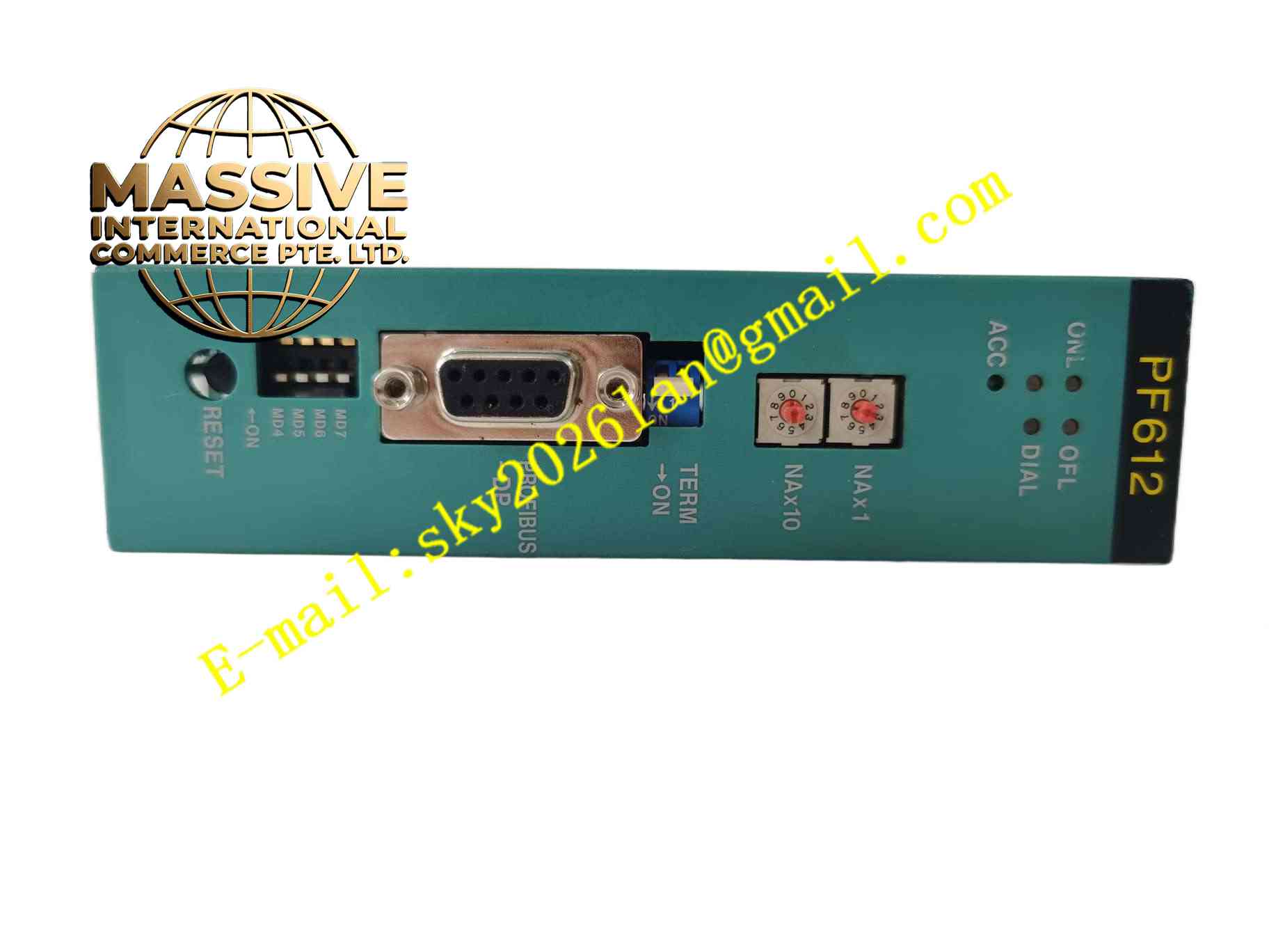
TOSHIBA PF612
Technical Specifications: Module type: Rack plug-in interface module Backplane interface: Toshiba proprietary rack backplane bus Power input: Rack backplane supplied power Signal channels: Multi isolated digital signal input and output channels Operating temperature range:0℃ ~ +60℃ Storage temperature range:-40℃ ~ +85℃ Relative humidity:5% to 95%, non-condensing Mounting form: Single slot plug-in rack card Protection grade:IP20 when installed inside control cabinet
Functional Features: Realize data and power transmission between rack backplane and internal control modules. Galvanic isolation for field digital signal channels to reduce noise interference. Front panel LED indicators display module power, running and fault status. Power-on self-test to verify internal circuit and backplane communication integrity. Continuous hardware self-diagnosis during runtime to detect internal circuit abnormality. Signal surge protection circuit protects backplane bus from field transient voltage. Support hot insertion and removal in compatible rack system.
Application Scenarios: Legacy power plant auxiliary control system, old chemical plant DCS rack system, water treatment retrofitted control cabinet, traditional manufacturing factory Toshiba automation rack system.
Performance Parameters: Stable backplane bus communication within rated operating temperature range. Isolation circuit blocks transient surge voltage from field signal wiring. Continuous 24-hour operation inside temperature controlled control cabinet. Self-diagnosis function reliably detects internal hardware fault.
Material Composition: PCB substrate: Multi-layer FR4 glass fiber epoxy printed circuit board with conformal coating. Core components: Bus communication logic IC, optocoupler isolation array, surge suppression components, power management chip. Front panel: Black flame retardant ABS plastic panel with silk screen and transparent LED windows. Backplane connector: Gold plated copper alloy edge contact pins.
Structural Features: Single width plug-in rack card structure compatible with Toshiba designated chassis. Front panel fitted with multi-color LED status indicators. Rear edge gold plated edge connector inserts into rack backplane slot. Internal circuit divided into backplane bus interface zone, power distribution zone and isolated signal conditioning zone. Mechanical locking latch secures module inside rack slot.
Working Principle: PF612 receives power supply and bus clock signal from rack backplane after inserting into rack slot. After power-on self-test completes, bus interface circuit establishes communication with rack main controller. Digital field signals enter module and pass through optocoupler isolation and surge protection circuit. Module transmits field status data to rack backplane and receives control commands from main controller, then forwards commands to field signal channels. Built-in diagnostic circuit continuously monitors power supply and communication status, triggers fault LED indicator when abnormality occurs.
Installation Requirements: Cut off rack power supply before inserting or removing PF612 module. Insert module into designated rack slot and fasten front mechanical latch. Check backplane connector pin condition before installation. Power on rack system and run module self-test. Ensure control cabinet protective earth connection is reliable. Reserve ventilation space around rack modules for heat dissipation.
Usage Notes: Backup rack system configuration before module replacement. Wear anti-static wristband during module handling. Do not hot swap module when rack is energized. Regularly inspect front panel LED indicators and backplane connector pins. Do not operate module outside rated temperature and humidity range. Prevent dust accumulation on gold plated backplane contact pins.