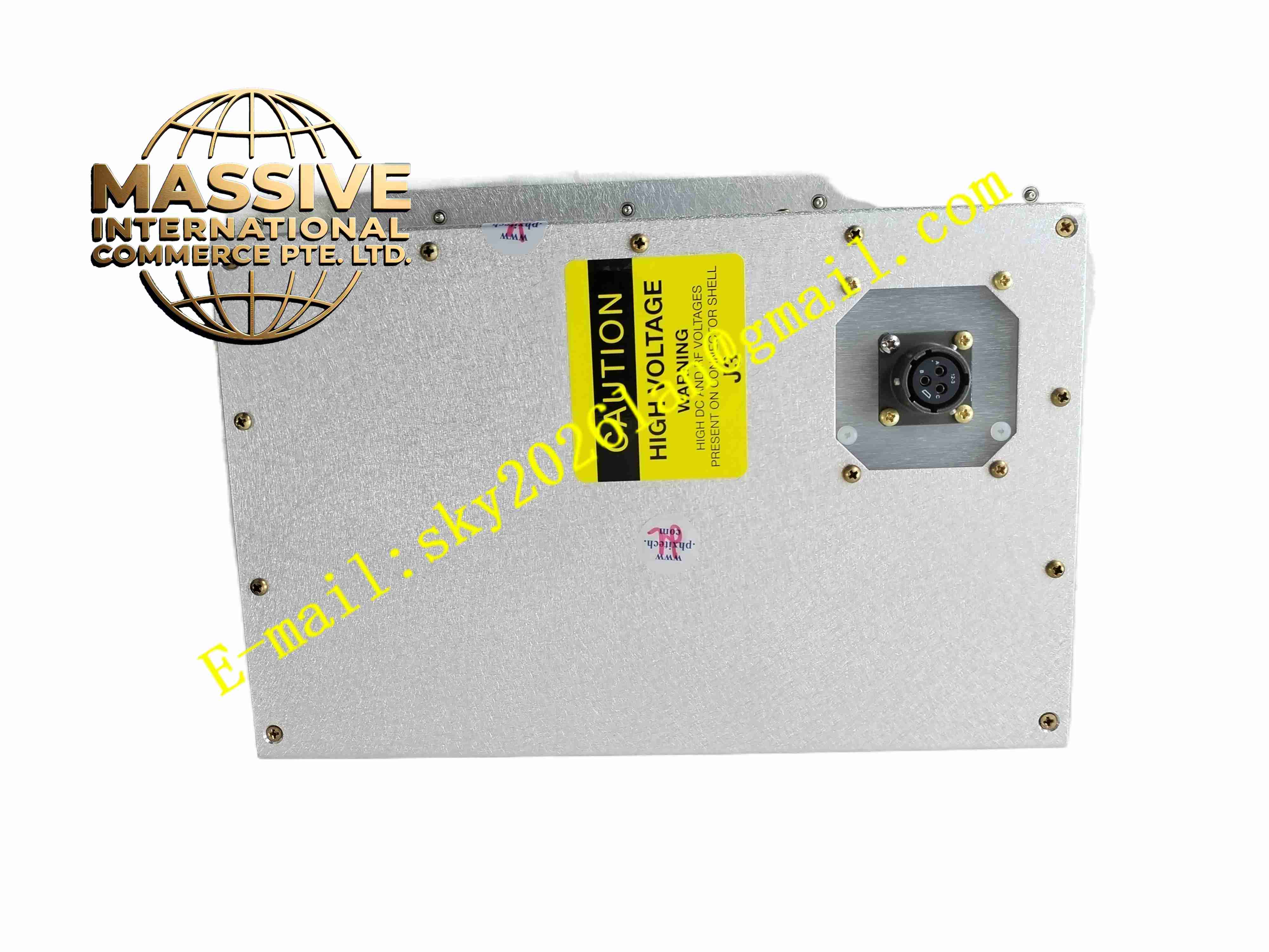
Description
TRAZAR ECC1-1
Technical Specifications
- Product Type: Embedded communication control module
- Power Supply: 24 VDC
- Analog Inputs: Multi-channel 4-20mA / 0-10V analog signal acquisition
- Digital I/O: Configurable discrete input and output channels
- Communication Interface: RS485 Modbus RTU, Ethernet
- Protection Rating: IP20 for board version; IP30 for enclosed version
- Operating Temperature: -20 °C to +60 °C
- Real-time Clock: Built-in RTC with battery backup
- Data Storage: Onboard non-volatile flash memory
- Mounting: Panel or DIN rail mounting
Functional Features
- Multi-channel analog signal sampling for pressure, temperature and vibration sensors.
- Digital input channel reading for discrete equipment status signals.
- Digital output channels for local alarm relay driving.
- Modbus RTU and Ethernet communication for data exchange with host PLC or SCADA.
- Onboard real-time clock records timestamp for collected data and alarm events.
- Non-volatile flash memory stores configuration parameters and historical data.
- Embedded local threshold alarm logic without continuous host system dependency.
- Built-in signal filtering to reduce noise interference from industrial field sensors.
- Watchdog timer automatically resets module upon firmware crash.
- Firmware upgradable via communication port for function expansion.
Application Scenarios
- Rotating machinery vibration monitoring systems
- Distributed process parameter data acquisition
- Pump and compressor condition monitoring
- Building energy consumption monitoring
- Factory floor remote sensor data collection
Material Composition
- Enclosure version housing: Aluminum alloy extrusion casing
- Circuit board: FR4 industrial PCB with surface mount components
- Signal chips: High precision analog-to-digital converter, MCU
- Terminals: Copper alloy spring terminals
- RTC battery: Lithium coin cell for time backup
- Insulation coating: Conformal coating for PCB protection
Structural Characteristics
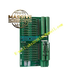
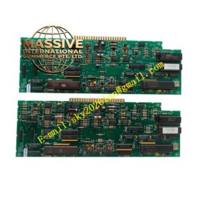
- Compact rectangular structure, available as bare PCB or enclosed aluminum housing.
- Front side equipped with LED indicators for power, communication and alarm status.
- Terminal block located on one edge for sensor and bus wiring.
- Internal PCB integrates analog front-end circuit, microcontroller and communication transceivers.
- Enclosed model has small ventilation slots for passive cooling.
- Multiple mounting holes for panel installation or DIN rail clip fitting.
Working Principle Field sensor analog and discrete signals enter the module’s signal front-end circuit. The analog-to-digital converter converts analog signals into digital values. The onboard microcontroller executes sampling, filtering and threshold comparison logic. Collected data is stored in flash memory and transmitted to upper host system via Modbus or Ethernet. When measured value exceeds preset threshold, the module triggers digital output alarm and timestamped event log. The watchdog circuit monitors MCU operation continuously and performs automatic reset if program halts.
Installation Requirements
- Install module inside control cabinet away from high heat sources.
- Use shielded twisted pair cable for analog sensor wiring.
- Separate analog signal cables from power cables.
- Complete 24VDC power wiring and protective earth connection.
- Set communication address and baud rate matching host system.
- Configure sensor type and measurement range during commissioning.
- Verify signal reading accuracy after installation.
Usage Notes
- Do not apply voltage exceeding input range to analog channels.
- Replace RTC backup battery periodically to preserve real-time clock.
- Prevent PCB contamination from dust and moisture.
- Use static protection when handling bare PCB version.
- Do not modify onboard circuit components.
- Backup configuration parameters before firmware upgrade.
- Perform regular signal calibration for long-term operation.