Description
UNIOP EKDC-16 6ZA933-7
Technical Specifications
- Product Type: 16-channel digital input module
- Number of Input Channels: 16 digital inputs
- Input Signal Type: 24 VDC sink/source digital signal
- Input Filter: Hardware input debounce filter for contact bounce suppression
- Bus Interface: Uniop internal backplane bus
- Protection Rating: IP20
- Operating Temperature: 0 °C to +60 °C
- Storage Temperature: -20 °C to +70 °C
- Indicator: Per-channel LED status indicator
- Mounting: DIN rail rack mounting
Functional Features
- 16 independent 24VDC digital input channels for reading field switch and sensor status.
- Hardware debounce filter eliminates false signal triggered by mechanical contact bounce.
- Individual LED indicator for each channel shows on/off input status.
- Backplane bus provides high speed data communication with Uniop host controller.
- Overvoltage and reverse polarity protection for each input channel.
- Galvanic isolation between field side and internal logic circuit.
- Hot swap capability within approved rack configuration.
- Compact modular design reduces cabinet space consumption.
- Channel diagnostic function detects wiring short circuit under certain conditions.
- Supports standard industrial 24VDC proximity sensors and limit switches.
Application Scenarios
- Automated assembly line field signal collection
- Packaging machinery discrete input acquisition
- Conveyor system limit switch and sensor monitoring
- Water treatment plant valve status feedback
- Building automation industrial remote I/O stations
Material Composition
- Module housing: Flame-retardant polycarbonate plastic
- Main PCB: FR4 industrial printed circuit board with conformal coating
- Input protection components: TVS diodes and current limiting resistors
- Optocouplers: Optical isolation chips for field and logic isolation
- Terminal block: Copper alloy spring cage terminals
- Backplane connector: Gold-plated copper contact pins
Structural Characteristics
- Vertical modular rack structure compatible with Uniop I/O rack.
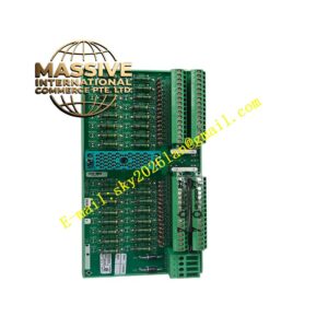
- Front panel contains 16 channel LED indicators and module status LED.
- Lower terminal block for field 24VDC input wiring.
- Rear gold-plated connector plugs into rack backplane bus.
- Optocoupler isolation separates field wiring side and controller logic circuit.
- Internal layout separates high voltage field circuits and low voltage bus logic.
Working Principle 24VDC discrete signals from field switches enter each input channel. Current limiting and overvoltage protection components protect the circuit. Optocouplers convert field side signal into isolated logic level signal for the module logic chip. The module scans all 16 channels continuously and transmits channel status data to host controller via backplane bus. Hardware debounce filter blocks transient bounce signals from mechanical switches to avoid false status changes. LED lights up when channel receives active input signal.
Installation Requirements
- Install module into Uniop I/O rack mounted on DIN rail.
- Use shielded twisted pair cable for field sensor wiring.
- Separate field input cables from high-power motor cables.
- Complete rack protective earth connection.
- Verify input wiring polarity for 24VDC sensors.
- Check backplane bus connection before power on.
- Test each channel by triggering field switches after commissioning.
Usage Notes
- Do not apply voltage exceeding 30VDC to input channels.
- Do not plug or unplug module when rack power remains active.
- Keep cabinet dry and free from conductive dust.
- Check terminal tightness periodically in vibrating environments.
- Use static protection when handling spare modules.
- Do not modify internal circuit components.
- Perform channel function test after field wiring overhaul.