Description
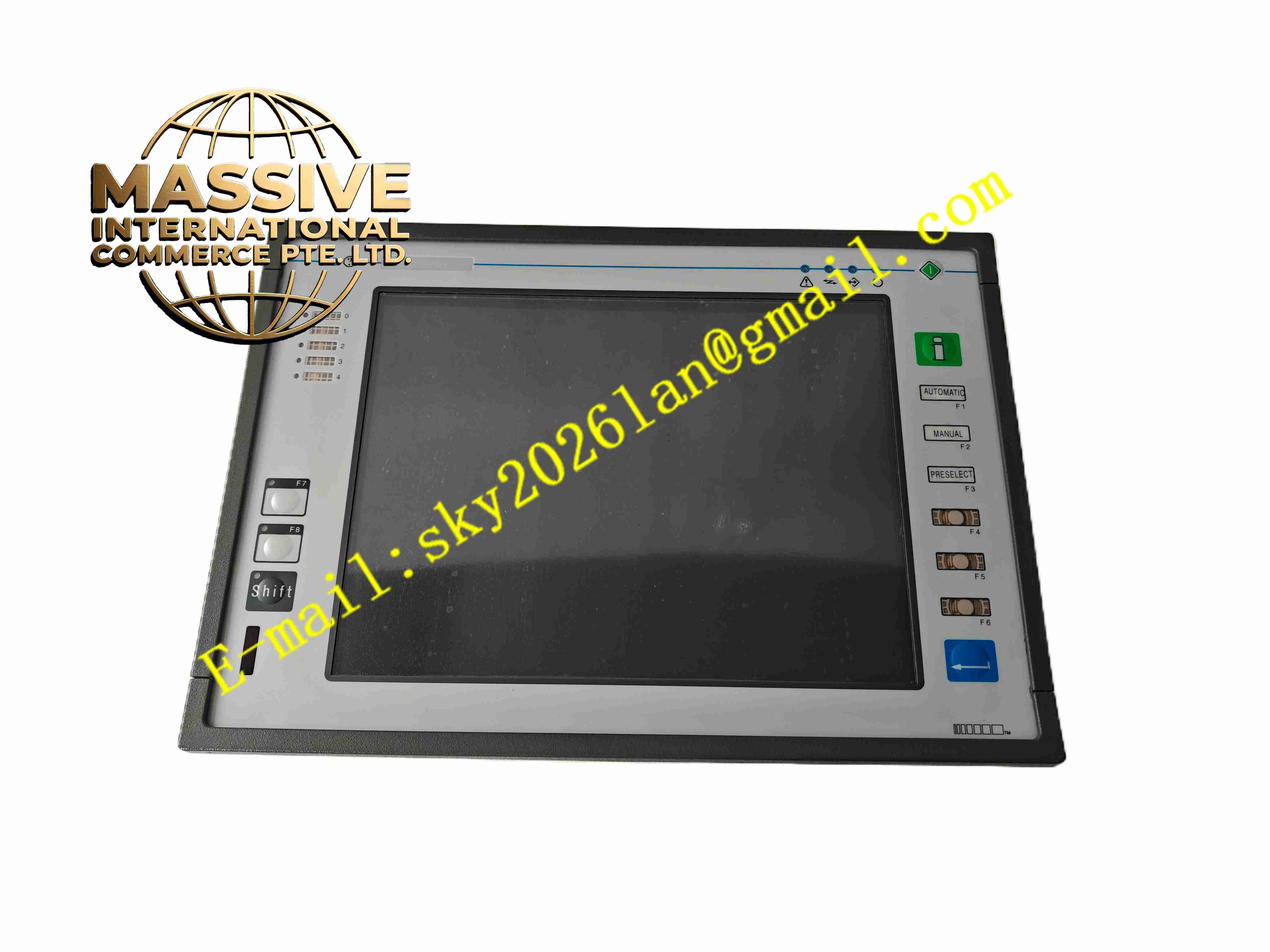
UNIOP ETT-VGA-0045
Technical Specifications
- Product Type: VGA industrial operator terminal
- Display Type: 10.4 inch VGA color LCD
- Display Resolution: 640 × 480 VGA
- Input: Resistive touchscreen plus dedicated physical function keys
- Power Supply: 24 VDC
- Communication: RS232, RS422, RS485 serial ports
- Protection Rating: Front panel IP65
- Operating Temperature: 0 °C to +50 °C
- Memory: Non-volatile flash memory for project and recipe storage
Functional Features
- Combined operation interface with touch screen and physical function keys for reliable operation in heavy vibration environment.
- Serial multi-protocol drivers support connection with various legacy PLC models.
- Recipe storage function saves multiple production parameter sets.
- Alarm event logging with timestamp stored in onboard flash memory.
- Built-in real-time clock for time stamp of alarms and logged data.
- User password protection prevents unauthorized modification of machine parameters.
- Configurable screen saver function to extend LCD backlight service life.
- On-screen keypad for numeric input and parameter adjustment.
- Support for bitmap graphics and animated machine status display.
- Remote project download via serial communication port.
Application Scenarios
- Legacy production line machine operator interface
- Metal processing machine control panel
- Material forming equipment local monitoring
- Paper and printing machinery HMI
- Old generation process control local operator station
Material Composition
- Front panel: Reinforced plastic frame with polycarbonate display window
- Touch element: Resistive touch membrane
- Function keys: Tactile membrane switch keys
- Main PCB: FR4 printed circuit board with conformal coating
- Rear housing: Flame-retardant plastic enclosure
- Sealing gasket: Foam rubber gasket for front panel sealing
Structural Characteristics
- Panel flush mounting structure for cabinet door cutout installation.
- Front surface integrates LCD display, touch area and arranged physical function keys.
- Rear casing contains PCB assembly, power terminal and serial communication connectors.
- Sealing gasket between front frame and cabinet door provides dust and splash protection.
- Rear mounting clips fix the panel to cabinet door.
- Internal layout isolates low voltage logic circuit from external wiring terminals.
Working Principle 24VDC power supplies the terminal hardware. The panel communicates with PLC via serial bus to continuously read register data. The main controller renders graphics, numerical values and alarm information on VGA LCD. Touch controller and physical key circuit capture operator operation events and transmit corresponding commands to PLC. Real-time clock provides timestamp for alarm and log entries. Flash memory retains project, recipe and event data after power loss.
Installation Requirements
- Prepare cabinet door cutout matching panel dimension drawing.
- Install sealing gasket before inserting panel into cabinet opening.
- Fasten rear mounting clips evenly.
- Use shielded twisted pair cable for serial communication wiring.
- Separate signal wiring from high-current power cables.
- Connect protective earth terminal to cabinet earth bar.
- Download HMI project and set communication parameters after wiring completion.
Usage Notes
- Avoid sharp objects contacting touch screen surface.
- Do not apply high pressure spray water directly onto front panel.
- Keep cabinet rear area dry and free of corrosive vapors.
- Backup project file before any firmware or project modification.
- Check communication cable connection periodically under vibration conditions.
- Replace backlight component once display brightness degrades.
- Perform periodic project backup for spare unit replacement.