Description
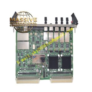
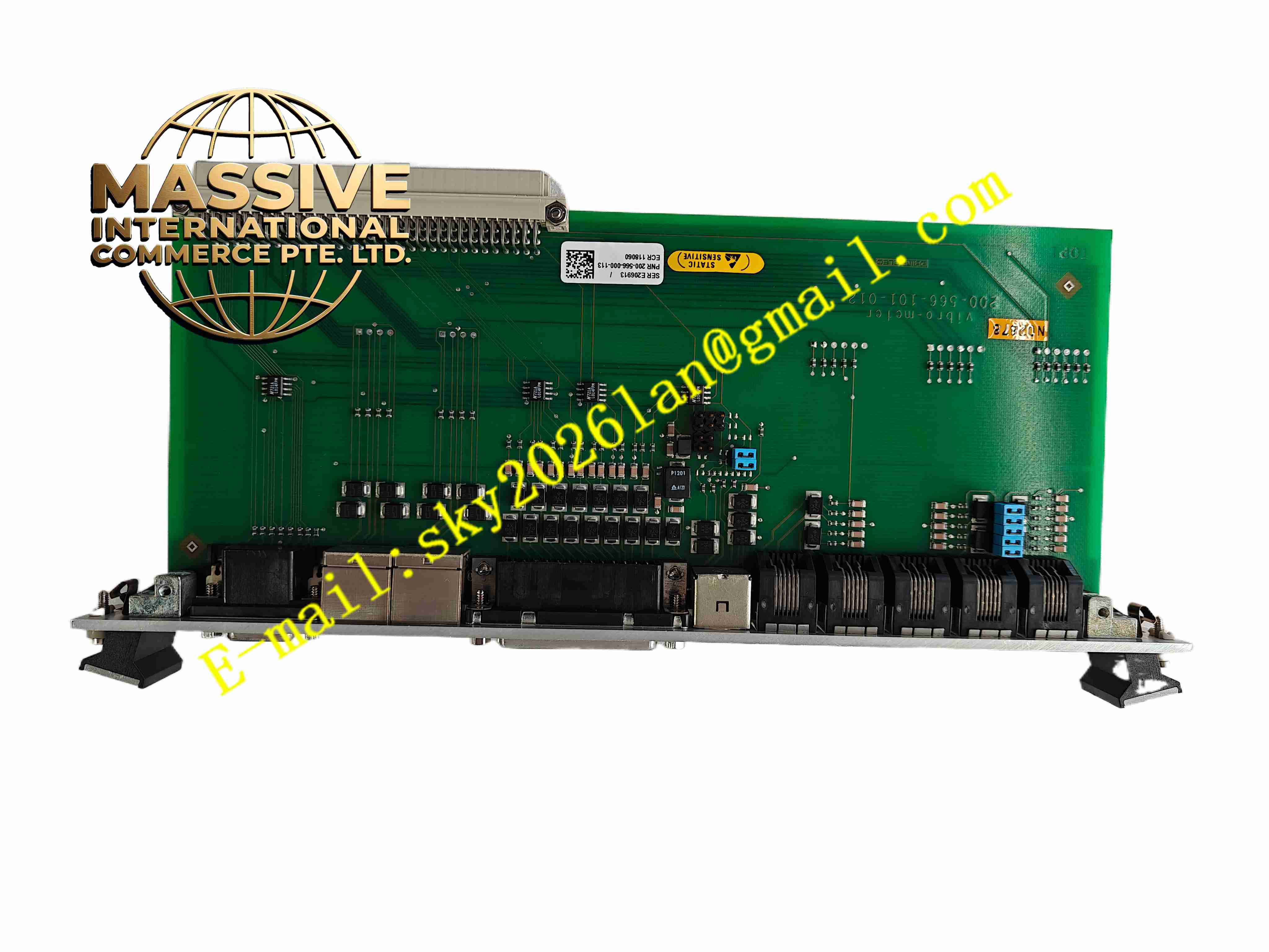
Vibro-Meter IOCN 200-566-000-113
Technical Specifications
- Product Type: VM600 network I/O plug-in card
- Communication Interface: Ethernet TCP/IP
- Signal Channels: Vibration and displacement transducer input channels, relay output channels
- Backplane Bus: VM600 rack internal bus
- Mounting: Plug-in module inside VM600 rack
- Protection Rating: IP00 for card, IP20 installed in cabinet
- Operating Temperature: 0 °C to +55 °C
- Humidity: 5 % to 90 %, non-condensing
- Weight: 0.42 kg
Functional Features
- Real-time vibration data acquisition from eddy current probes, accelerometers and velocity sensors.
- Ethernet interface transmits waveform, vibration magnitude and alarm status to SCADA or monitoring workstation.
- Internal rack bus exchanges data with MPC4 machinery protection processor card.
- Relay output channels transmit alarm and trip status to plant DCS system.
- Sensor wire break and short circuit fault detection for each input channel.
- Galvanic isolation reduces ground loop interference between field sensors and rack.
- Front panel LED indicators show Ethernet link, power and channel fault status.
- Hot swap function allows card replacement during planned equipment shutdown.
- Conformal coating protects PCB for industrial cabinet environment.
- Built-in data buffer stores transient waveform data during machine trip event.
Application Scenarios
- Steam turbine bearing vibration monitoring network interface
- Gas turbine machinery protection data communication
- Large centrifugal compressor vibration online monitoring
- Power plant generator shaft position and vibration measurement
- Refinery rotating machinery condition monitoring system
Material Composition
- Main PCB: FR4 printed circuit board with conformal coating
- Signal conditioning: Precision amplifier and filter components
- Ethernet controller: Industrial Ethernet transceiver chip
- Backplane connector: Gold plated edge contact pins
- Front panel: Flame retardant plastic with LED indicators and Ethernet connector
- Surge protection components: Transient suppression diodes and current limiting resistors
Structural Characteristics
- Slim plug-in rack card with front panel Ethernet port and LED indicators.
- Rear gold plated edge connector inserts into VM600 rack backplane bus.
- Independent signal conditioning circuit for each sensor input channel.
- Internal isolation barrier separates field sensor circuit and digital network circuit.
- Passive convection cooling without fan.
Working Principle Vibration and position signals from field transducers enter IOCN card. Signal conditioning circuit filters and amplifies raw signals. The card transfers processed measurement data to MPC4 protection card via rack bus. Meanwhile, the card packages vibration magnitude, waveform and alarm event data, transmits to upper monitoring workstation via Ethernet TCP/IP. Channel diagnostic circuit continuously monitors sensor loop impedance and reports wiring fault. Relay output activates when vibration value exceeds alarm threshold defined in MPC4 card.
Installation Requirements
- Insert IOCN card into designated slot of Vibro-Meter VM600 rack.
- Connect field sensor wiring to rack termination block.
- Use shielded twisted pair cable for sensor wiring and Ethernet network cable.
- Separate sensor signal cable from high power motor cables.
- Complete protective earth connection for VM600 rack.
- Configure network IP address and channel parameters in configuration software.
- Test Ethernet data transmission and alarm relay function after wiring completion.
Usage Notes
- Do not apply overvoltage to sensor input terminals.
- Keep cabinet environment free of oil mist and conductive dust.
- Backup project configuration before card replacement.
- Disconnect rack power before extracting or inserting card.
- Use anti-static wristband when handling spare card.
- Replace card immediately when permanent Ethernet communication or signal acquisition fault occurs.