Description
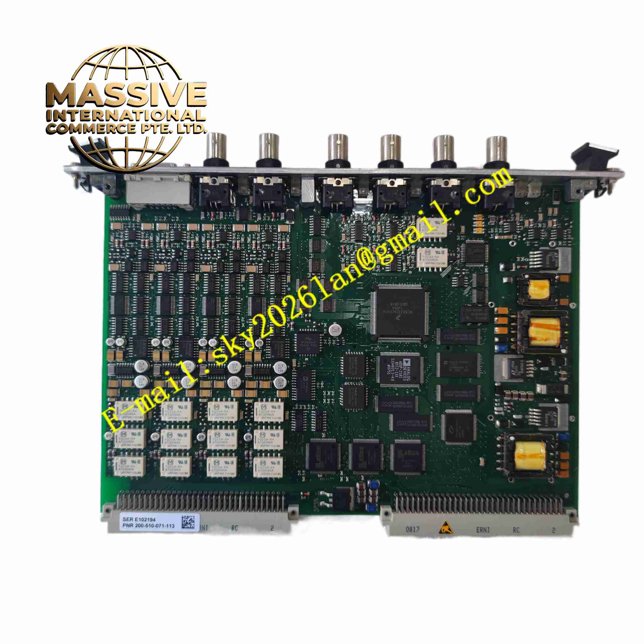
Vibro-Meter MPC4 200-510-071-113
Technical Specifications
- Brand: Vibro-Meter
- Product Family: VM600 Machinery Protection System
- Card Type: Machinery Protection Card MPC4
- Ordering Number: 200-510-071-113
- Dynamic Input Channels: 4 per card
- Speed/Tachometer Channels: 2 per card
- Sensor Compatibility: Proximity probes, velocity sensors, IEPE accelerometers, and displacement transducers used in VM600 systems
- DC Input Range: 0 to +20 V or 0 to -20 V
- AC Input Range: Up to ±10 V
- Common-Mode Voltage Range: -50 V to +50 V
- CMRR: Greater than 60 dB at 50 Hz
- Crosstalk: -72 dB
- Input Impedance: 200 kΩ
- Vibration Frequency Range: 0.1 Hz to 10 kHz
- Gap/Position Frequency Range: DC to 1 Hz
- Amplitude Accuracy: ±1% of full scale for vibration and gap/position
- Linearity Error: Less than ±1%
- Power Supply: Supplied through the VM600 rack backplane
- Operating Temperature: Typically 0°C to +55°C in a ventilated control cabinet; exact limits depend on the installed VM600 rack configuration
- Physical Size: 6U height, 20 mm width, 187 mm depth
- Weight: Approximately 0.40 kg
Functional Features
- Four dynamic channels: Accepts vibration, displacement, acceleration, velocity, and position signals.
- Two tachometer channels: Supports speed reference, phase measurement, and order tracking.
- DSP-based processing: Uses digital signal processing for filtering, integration, differentiation, and rectification.
- Programmable filters: Supports broadband and narrowband measurement.
- Amplitude and phase monitoring: Enables vibration severity and phase-angle evaluation.
- Adaptive alarm levels: Alert and Danger setpoints can adapt to speed or external process conditions.
- Buffered BNC outputs: Front-panel BNC connectors provide buffered raw sensor signals for analysis.
- Hot-swappable design: Allows replacement without shutting down the entire VM600 rack.
- Self-diagnostics: Performs power-up self-test and continuous measurement-chain monitoring.
- SIL-capable variants: SIL-certified versions are available within the MPC4 family for safety-related applications.
Application Scenarios
- Steam turbine vibration and axial position monitoring
- Centrifugal compressor protection
- Fan and blower condition monitoring
- Pump bearing and shaft vibration monitoring
- Gearbox vibration and speed monitoring
- Power generation, oil and gas, petrochemical, and industrial rotating equipment protection
Performance Parameters
- Measurement Channels: 4 dynamic plus 2 speed channels
- Signal Processing: Real-time DSP measurement
- Alarm Outputs: Digital alarm signals routed to IOC4T or relay modules in the VM600 rack
- Analog Outputs: 0 to 10 V and 4 to 20 mA outputs available through the associated IOC4T card
- Relay Outputs: Provided by IOC4T, RLC16, or IRC4 relay cards in the system
- Response Behavior: Determined by configured filter, alarm delay, hysteresis, and latch settings
- System Integration: Communication handled at the rack level via Ethernet, Modbus, or other rack interface modules
Material Composition
- PCB Assembly: Industrial-grade printed circuit board with DSP and signal-conditioning circuits
- Front Panel: Metal faceplate with BNC connectors and LED indicators
- Connectors: Backplane connector for rack integration
- Internal Components: Analog input stages, digital processors, power regulation circuits, and diagnostic circuits
- Housing: No separate external housing; the card is mounted inside a 19-inch rack
Structural Features
- 6U Eurocard format: Fits into a ABE04x rack slot.
- 20 mm slot width: Occupies one module position in the rack.
- Front-panel BNC connectors: Allow direct access to buffered sensor signals.
- LED indicators: Show channel status, alarm conditions, and card health.
- Card-pair architecture: Operates together with an IOC4T input/output card.
- Hot-plug capability: Supports removal and insertion during rack operation when system procedures permit.
Working Principle
Sensor signals from proximity probes, accelerometers, or velocity transducers are fed into the MPC4 dynamic input channels. The card conditions the signals, applies digital filtering, and calculates vibration amplitude, gap, position, speed, and phase. Tachometer channels provide rotational speed reference for order tracking and adaptive alarm evaluation. When measured values exceed programmed Alert or Danger thresholds, the card generates alarm signals that are sent to IOC4T and relay modules. These relay outputs can trigger warnings, process interlocks, or machine shutdown.
Installation Requirements
- Install the MPC4 card into a compatible rack such as ABE040, ABE042, or ABE056.
- Pair the MPC4 with the correct IOC4T input/output card as required by the configuration.
- Verify that the rack power supply and backplane are correctly installed.
- Connect sensor cables to the appropriate terminal modules or interfaces.
- Configure channel types, sensor sensitivity, filter settings, and alarm setpoints in the software.
- Use shielded instrumentation cables for sensor connections.
- Confirm LED status and buffered BNC signals during commissioning.
Precautions for Use
- Do not insert or remove the card unless the system procedures allow hot swapping.
- Ensure the correct card is installed as the paired I/O module.
- Do not exceed the rated sensor input ranges.
- Verify alarm setpoints, delays, and relay actions before placing the machine under automatic protection.
- Keep the rack ventilation unobstructed to maintain the specified operating temperature.
- Use only compatible racks, power supplies, and interface cards.
- For exact channel mapping, alarm logic, and certification details for part number 200-510-071-113, refer to the official Vibro-Meter documentation.