Description
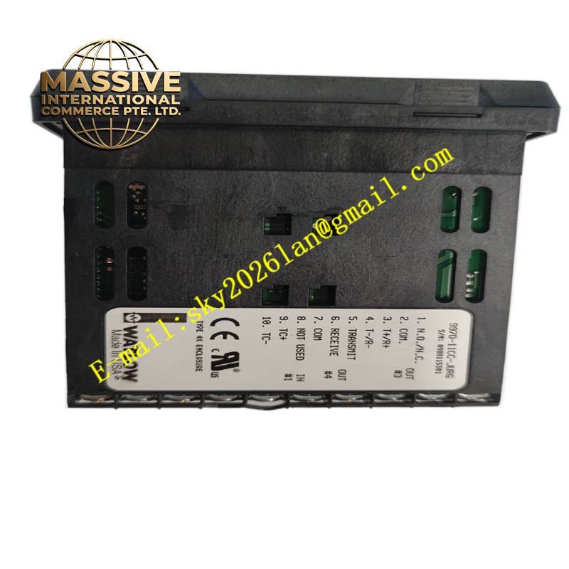
Watlow 997D-11CC-JURG
Technical Specifications Supports multiple sensor input types including thermocouple and RTD; built-in PID self-tuning function; relay and logic level output options; digital display and key operation interface; wide working voltage range; multiple alarm modes.
Functional Features Collects temperature sensor signals and compares measured temperature with set temperature value. PID algorithm automatically adjusts output power to stabilize process temperature. Supports automatic tuning of PID parameters to adapt to different thermal load characteristics. Multiple alarm functions realize overtemperature, sensor break and deviation alarm. The digital display screen shows real-time temperature and set value.
Application Scenarios Industrial furnace, plastic extrusion equipment, packaging heat sealing machine, environmental test chamber, semiconductor heating process and laboratory heating equipment.
Performance Parameters High temperature measurement accuracy; stable PID regulation; fast response to temperature change; clear digital display and stable key recognition.
Material Composition Shell is flame-retardant plastic; internal PCB uses FR-4 substrate; signal conditioning and control chips are industrial grade; terminal block is nickel-plated conductive terminal with insulating plastic base; display window is transparent scratch-resistant panel.
Structural Characteristics Standard panel mounting rectangular structure; front panel equipped with digital display screen and function keys; rear part with wiring terminal block for sensor, power supply and output load; panel installation buckle for embedded installation in equipment cabinet door.
Working Principle The temperature sensor transmits temperature signal to the controller’s signal input circuit. After signal conversion and A/D sampling, the controller compares the measured value with the set value. The PID operation unit calculates the required output and drives the load to heat or cool. When the temperature exceeds the threshold, the controller triggers the alarm output.
Installation Requirements Embed the controller into the opening of the equipment control panel and fasten the installation buckle. Connect sensor wires, power wires and load output wires to corresponding terminals according to the wiring diagram. Select sensor type and set temperature range before use, and complete PID auto-tuning.
Precautions for Use Do not install in places with strong corrosive gas, excessive humidity and direct high heat radiation. Sensor cables should be separated from power cables. Do not exceed the rated load capacity of the output terminal. Replace the sensor immediately when the temperature display is abnormal.