Description
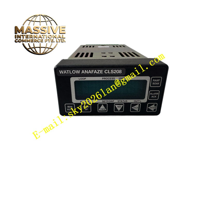
Watlow CLS208
Technical Specifications Total control loops: 8; supporting input types include thermocouple, 2/3-wire RTD, voltage, current and frequency signals; resolution of analog conversion reaches 16-bit; communication interfaces include EIA/TIA-232 and EIA/TIA-485; power supply range 12 to 24 VDC; operating temperature range -20 ℃ to +60 ℃; front panel with two-line 16-character display and tactile membrane keys; optional ramp-and-soak and enhanced algorithm packages for cascade, ratio and differential control.
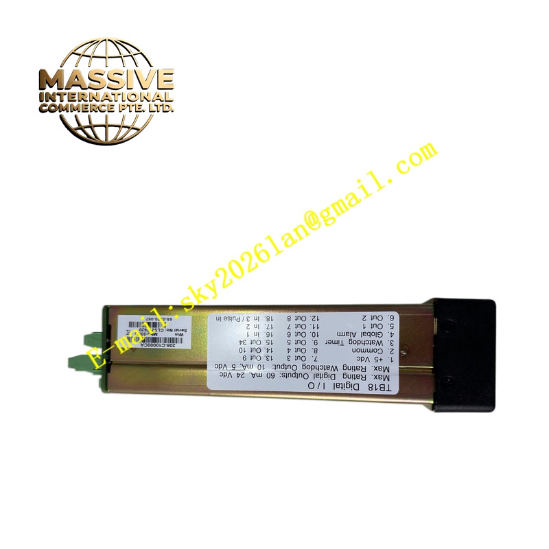
Functional Features Each loop executes independent PID calculation with auto-tuning function; ramp-and-soak profile scheduling handles batch thermal cycles; HART-compatible signal conditioning supports transmitter signal retransmission; hardware channel fault detection identifies open sensor wires and out-of-range variables; digital output assignment is flexible for SSR, relay or logic drive; serial communication enables remote setpoint modification, parameter upload and historical data extraction.
Application Scenarios Semiconductor thermal processing furnaces, packaging heat sealing equipment, environmental test chambers, plastic extrusion temperature zones, pharmaceutical lyophilization processes.
Material Composition Flame-retardant ABS plastic enclosure; FR4 multilayer signal printed circuit board; high-precision ADC and DAC conversion chips; membrane tactile key panel; gold-plated SCSI or 50-pin terminal connectors.
Structural Characteristics 1/8 DIN panel mounting form factor; front display and keyboard assembly; rear connector interface supporting SCSI cable or 50-pin termination board; internal board layout separates analog sensor signal circuits and digital communication circuits to reduce crosstalk.
Working Principle The controller samples raw sensor signals from each loop, converts analog measurements into digital process variable values. PID algorithms compare measured values with setpoints and calculate control output levels to regulate heating or cooling actuators. Profile sequences stored in nonvolatile memory change setpoints automatically according to time schedules. Process data is transmitted to supervisory hosts through serial channels.
Installation Requirements Mount into standard 1/8 DIN instrument cutout on control panel; use shielded twisted pair wiring for thermocouple and RTD sensors; single-point grounding of cable shield inside control cabinet; maintain clearance around the unit for convection cooling; configure serial communication jumper before power application.
Operation Notes Switch control loops to manual mode before modifying channel hardware jumpers; back up all thermal profiles and PID parameters before firmware replacement; avoid exposure to oil vapor and condensed moisture; verify sensor linearization curve after sensor type replacement.