Description
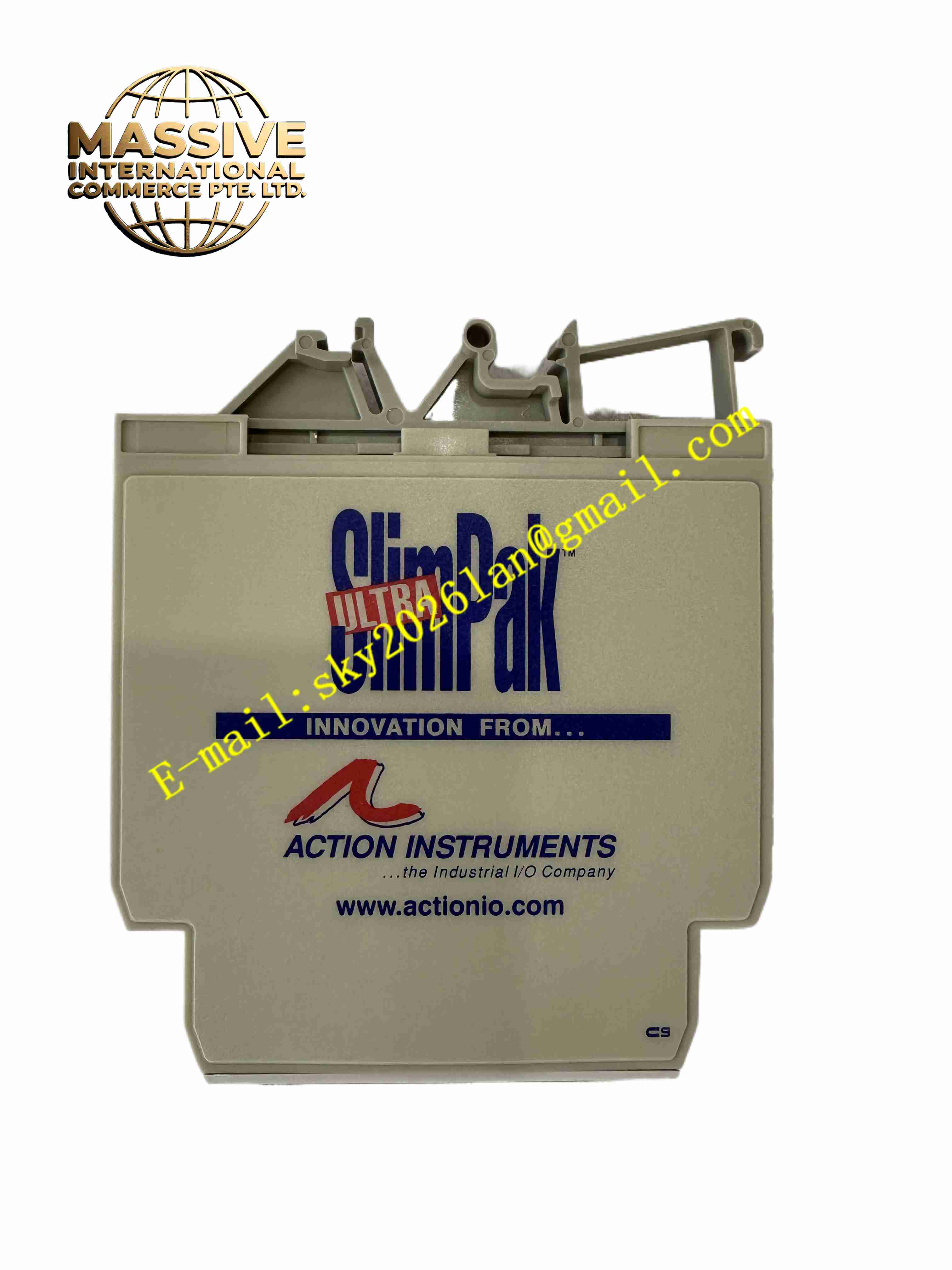
WATLOW G408-0001
Technical Specifications:
- Power Supply: 9 VDC to 30 VDC, 24 VDC typical
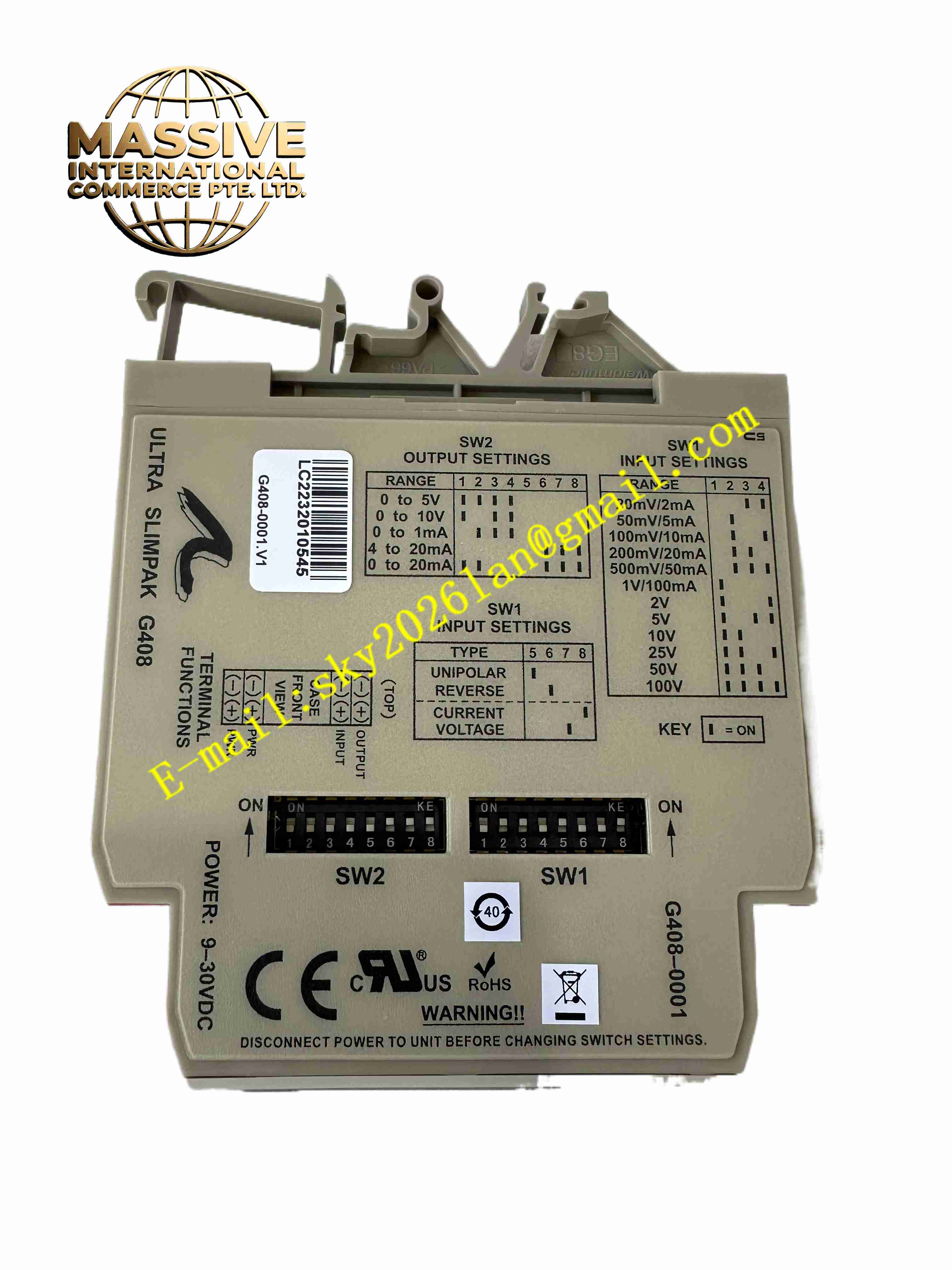
- Input Ranges: 18 configurable ranges including 1 mV to 100 V voltage, 1 mA to 100 mA current
- Default Factory Setting: 4–20 mA input, 4–20 mA output
- Output Ranges: 0–5 V, 0–10 V, 0–1 mA, 0–20 mA, 4–20 mA selectable
- Isolation: Galvanic isolation between input side, output side and power supply
- Zero Adjustment: 50% full scale zero trim
- Span Adjustment: 50% full scale span trim
- Accuracy: High linearity for analog signal transmission
- Operating Temperature: -20 °C to +60 °C
- Storage Temperature: -40 °C to +85 °C
- Mounting: DIN rail mounting
Function Features:
- Galvanic isolation breaks ground loop interference in analog signal loops
- Field configurable input and output signal ranges by DIP switches
- Zero and span trim potentiometers for on-site calibration
- Linear signal conversion between selected input and output ranges
- Protect DCS and PLC analog input cards from field side surge and common mode voltage
- Compact DIN rail form factor for cabinet installation
- No software required, all configuration via hardware switches
- Continuous signal transfer without digital conversion delay
Application Scenarios:
- Chemical plant 4–20 mA transmitter signal isolation
- Power plant DCS analog input signal conditioning
- Refinery process measurement signal isolation
- Water treatment plant analog signal transmission
- Industrial furnace and thermal process control signal isolation
Material Composition:
- Housing: Flame retardant plastic DIN rail enclosure
- Main PCB: FR4 fiberglass printed circuit board
- Core Components: Isolation transformers, analog signal conditioning circuits
- Terminals: Screw copper terminal blocks for input, output and power wiring
- Adjustment Components: Multi-turn zero and span trim potentiometers, DIP switch bank
- Passive Components: Precision resistors, capacitors and surge suppression devices
Structural Features:
- Compact rectangular DIN rail snap-on housing
- Screw terminal blocks on the top and bottom for field wiring
- Removable housing cover for access to DIP switches and trim potentiometers
- Internal isolation barrier separates input circuit, output circuit and power circuit
- DIN rail clip integrated on rear side of enclosure
Working Principle: DC analog input signal enters the isolator input terminals. The signal conditioning circuit converts input signal into proportional isolated intermediate signal across galvanic isolation barrier. The isolated circuit reconstructs linear analog output signal according to selected output range. Isolation barrier blocks common mode voltage and eliminates ground loop current between field transmitter and control system. Zero and span potentiometers adjust offset and gain to match required measurement range.
Installation Requirements:
- Mount isolator on standard 35 mm DIN rail inside control cabinet
- Use shielded twisted pair cables for input and output analog wiring
- Separate low-level analog signal cables from high voltage power cables
- Supply 9–30 VDC power and connect protective earth
- Keep cabinet ambient temperature within -20 °C to +60 °C
- Avoid installation location with corrosive gas and heavy moisture
Usage Notes:
- Set DIP switches for required input and output ranges before power on
- Perform zero and span calibration after wiring modification
- Verify signal polarity during wiring
- Do not exceed maximum input voltage and current limits
- Disconnect power before opening housing cover to adjust switches and trims
- Check terminal screw tightness periodically to prevent loose analog signal connections