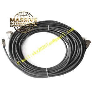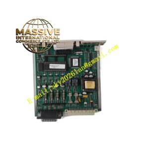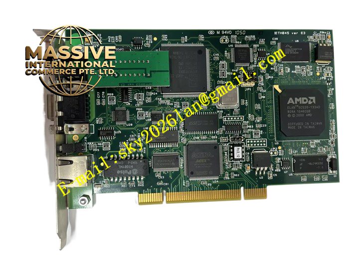
Description
Woodhead PCU-DPIO
Technical Specifications: Module type: Distributed digital input and output module Digital input channels: Multi-channel 24VDC sink/source digital inputs Digital output channels: Multi-channel 24VDC digital outputs Fieldbus interface: Industrial fieldbus communication port Field power supply: 24 VDC Operating temperature range:-20℃ ~ +60℃ Storage temperature range:-40℃ ~ +85℃ Relative humidity:5% to 95%, non-condensing Mounting type: DIN rail or machine surface mounting Protection grade:IP67 for field installation version
Functional Features: Collect binary on-off status from field proximity switches, limit switches and relay auxiliary contacts. Output 24VDC switching signal to drive solenoid valves, indicator lights and small contactors. Built-in surge and ESD protection for each field signal channel. Fieldbus communication transmits I/O status data to main PLC controller and receives output commands. Front panel LED status indicators for each individual input and output channel. Power-on self-test and continuous channel fault diagnosis function. Sealed housing allows installation close to field machines instead of central control cabinet. Support hot swapping in compatible fieldbus system.
Application Scenarios: Distributed remote I/O for conveyor systems, packaging machinery field signal collection, automotive assembly line machine side I/O, material handling equipment, valve bank feedback and control, machine safety switch signal acquisition.
Performance Parameters: Fast input signal state capture for high-speed discrete switching signals. Stable output switching under rated load current condition. Built-in surge protection absorbs transient voltage spikes generated by inductive field loads. Continuous stable operation in dusty and vibration-prone workshop environment. Reliable fieldbus data transmission under industrial electromagnetic noise.
Material Composition: PCB substrate: Multi-layer FR4 glass fiber epoxy printed circuit board with conformal coating. Core components: Digital logic IC, fieldbus communication transceiver, optocoupler isolation chips, ESD and surge suppression components. Housing: Reinforced flame retardant glass filled plastic sealed enclosure. Field connectors: Metal shielded industrial circular connectors with gold-plated contacts.
Structural Features: Compact rectangular sealed enclosure structure suitable for machine surface or DIN rail mounting. External circular industrial connectors for field sensor, actuator and fieldbus wiring. Front panel LED indicators correspond to each I/O channel for visual status check. Internal circuit divided into field signal conditioning zone, logic control zone and fieldbus communication zone. Internal conformal coating protects PCB against moisture, dust and corrosive gas in field environment.
Working Principle: 24VDC field power supplies PCU-DPIO module hardware. Field digital signals enter module through circular connectors, pass through surge protection and optocoupler isolation circuit, then send on-off state to logic control chip. Logic chip transmits input status data to PLC controller via fieldbus. When main controller sends output command through fieldbus, logic chip activates corresponding output circuit to switch 24VDC power to field actuators. LED indicators reflect real-time channel state. Conformal coating and sealed housing protect internal circuit from field environmental contamination.
Installation Requirements: Cut off 24VDC field power before module installation and wiring. Mount PCU-DPIO module on machine surface or DIN rail at field equipment side. Connect field sensors, actuators and fieldbus cable to circular connectors. Set fieldbus address and communication parameters in PLC programming software. Power on field power supply and download project configuration. Verify input signal reading and output switching performance. Connect module protective earth terminal to local machine grounding point. Use shielded fieldbus cable for communication wiring.
Usage Notes: Use freewheeling diode when driving inductive loads such as solenoid valves. Do not exceed rated output current of each digital output channel. Check circular connector sealing gasket integrity after wiring and assembly. Backup PLC project before adding this remote I/O module. Do not operate module outside rated temperature and humidity range. Inspect connector locking status periodically to prevent loose connection.